DESCRIPTION If the vehicle has been stopped without opening or closing the driver door for a long period of time, the electronically controlled brake system will not be ready and sufficient fluid pressure may not be stored in the accumulator. In this case, the brake pedal response may not be the same as usual the first time the brake pedal is depressed. This is not a malfunction. WIRING DIAGRAM 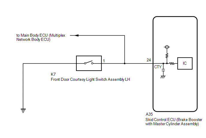 CAUTION / NOTICE / HINT NOTICE: After replacing the skid control ECU (brake booster with master cylinder assembly), perform linear solenoid valve offset learning, ABS holding solenoid valve learning, yaw rate and acceleration sensor zero point calibration and system information memorization after performing "Reset Memory". Click here PROCEDURE
(a) Check the conditions at the time the problem occurred. (1) Whether a warning light illuminated or the buzzer sounded. (2) The number of times the power switch was turned on (IG) since the latest symptom occurred. (3) Frequency of the symptom.
(a) Clear the DTCs. Click here
(b) Turn the power switch off. (c) Turn the power switch on (IG). (d) Check the DTCs (electronically controlled brake system) that are output. Click here
(a) Turn the power switch off. (b) Depress the brake pedal within 2 minutes of opening the driver door and check the response of the brake pedal. (c) Release the brake pedal and wait for 2 minutes without depressing the brake pedal, opening or closing the driver door or operating the power switch. (d) After 2 seconds or more have elapsed, depress the brake pedal and check that the first depression response is different to successive depression responses. HINT: Compare the response of the brake pedal when the system is in sleep mode and when the stroke simulator is operating.
(a) Set the interior light door switch to ON and check that the map light assembly illuminates, then set the interior light door switch to DOOR. (b) Check that the map light assembly illuminates when the driver door is opened. OK: The map light assembly illuminates when the driver door is opened.
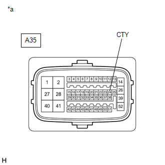
(b) Disconnect the A35 skid control ECU (brake booster with master cylinder assembly) connector. (c) Check both the connector case and the terminals for deformation and corrosion. OK: No deformation or corrosion. (d) Measure the voltage according to the value(s) in the table below. Standard Voltage:
|
Toyota Avalon (XX50) 2019-2022 Service & Repair Manual > 2gr-fks Battery / Charging: Battery
ComponentsCOMPONENTS ILLUSTRATION *1 BATTERY *2 NEGATIVE BATTERY TERMINAL *3 POSITIVE BATTERY TERMINAL *4 NO. 2 BATTERY CLAMP *5 BATTERY TERMINAL CAP - - Tightening torque for "Major areas involving basic vehicle performance such as moving/turning/stopping": N*m (kgf*cm, ft.*lbf) N*m (kgf*cm, ft.*l ...