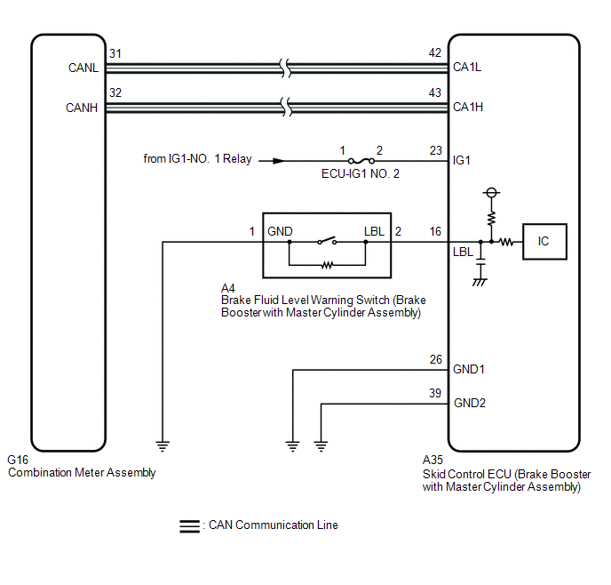
DESCRIPTION The skid
control ECU (brake booster with master cylinder assembly) is connected
to the combination meter assembly via CAN communication. If any of the following is detected, the brake warning light / red (malfunction) remains on:
- The skid control ECU (brake booster with master cylinder assembly)
connector is disconnected from the brake booster with master cylinder
assembly.
- The brake fluid level is insufficient.
- EBD operation has been disabled.
WIRING DIAGRAM
 CAUTION / NOTICE / HINT
NOTICE:
- After replacing the skid control ECU (brake booster with master cylinder
assembly), perform linear solenoid valve offset learning, ABS holding
solenoid valve learning, yaw rate and acceleration sensor zero point
calibration and system information memorization after performing "Reset
Memory".
Click here 
- Inspect the fuses for circuits related to this system before performing the following procedure.
- Before performing this procedure, depress the brake pedal and confirm that the stop lights illuminate.
PROCEDURE (a) Check that all of the following conditions required for the brake warning light / red (malfunction) to turn off are met:
|
NEXT |
 | |
(a) Check if ABS, VSC and/or electronically controlled brake system DTCs are output.
Click here Chassis > ABS/VSC/TRAC > Trouble Codes
|
Result | Proceed to | |
DTCs are not output. |
A | | DTCs are output. |
B |
| B |
 | REPAIR CIRCUITS INDICATED BY OUTPUT DTCS |
|
A | |
| |
| 3. |
CHECK CAN COMMUNICATION SYSTEM | (a) Check if CAN communication system DTCs are output.
Click here
|
Result | Proceed to | |
DTCs are not output. |
A | | DTCs are output. |
B |
| B |
| INSPECT CAN COMMUNICATION SYSTEM |
|
A | |
| |
| 4. |
CHECK IF BRAKE BOOSTER WITH MASTER CYLINDER ASSEMBLY CONNECTOR IS SECURELY CONNECTED |
(a) Check if the skid control ECU (brake booster with master cylinder assembly) connector is securely connected.
OK: The connector is securely connected.
| NG |
| CONNECT CONNECTOR TO BRAKE BOOSTER WITH MASTER CYLINDER ASSEMBLY CORRECTLY |
|
OK | |
| |
| 5. |
CHECK AUXILIARY BATTERY | (a) Check the auxiliary battery voltage.
Standard Voltage: |
Tester Connection | Condition |
Specified Condition | |
Auxiliary battery | Power switch on (IG) |
11 to 14 V | |
Auxiliary battery | Power switch on (READY) |
11 to 15.5 V |
| NG |
| CHARGE OR REPLACE AUXILIARY BATTERY |
|
OK | |
| |
| 6. |
CHECK HARNESS AND CONNECTOR (IG1 TERMINAL) |
| (a) Turn the power switch off. |
 |
|
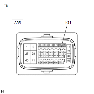
*a | Front view of wire harness connector
(to Skid Control ECU (Brake Booster with Master Cylinder Assembly)) | | |
(b) Make sure that there is no looseness at the locking part and the connecting part of the connector.
OK: The connector is securely connected. (c) Disconnect the A35 skid control ECU (brake booster with master cylinder assembly) connector.
(d) Check both the connector case and the terminals for deformation and corrosion.
OK: No deformation or corrosion. (e) Turn the power switch on (IG).
(f) Measure the voltage according to the value(s) in the table below. Standard Voltage: |
Tester Connection | Condition |
Specified Condition | |
A35-23 (IG1) - Body ground |
Power switch on (IG) |
11 to 14 V |
| NG |
| REPAIR OR REPLACE HARNESS OR CONNECTOR (IG1 CIRCUIT) |
|
OK | |
| |
| 7. |
CHECK HARNESS AND CONNECTOR (GND TERMINAL) |
| (a) Turn the power switch off. |
 |
|
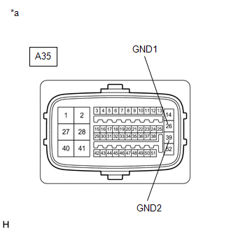
*a | Front view of wire harness connector
(to Skid Control ECU (Brake Booster with Master Cylinder Assembly)) | | |
(b) Measure the resistance according to the value(s) in the table below.
Standard Resistance: |
Tester Connection | Condition |
Specified Condition | |
A35-26 (GND1) - Body ground |
Always | Below 1 Ω | |
A35-39 (GND2) - Body ground |
Always | Below 1 Ω |
| NG |
| REPAIR OR REPLACE HARNESS OR CONNECTOR (GND CIRCUIT) |
|
OK | |
| |
| 8. |
READ VALUE USING TECHSTREAM (BRAKE WARNING LIGHT / RED (MALFUNCTION)) |
(a) Reconnect the A35 skid control ECU (brake booster with master cylinder assembly) connector.
(b) Select the Data List on the Techstream. Click here
Chassis > ABS/VSC/TRAC > Data List
|
Tester Display | Measurement Item |
Range | Normal Condition |
Diagnostic Note | |
Brake Warning Light | Brake warning light / red (malfunction) |
ON or OFF | ON: Warning light on
OFF: Warning light off |
- | Chassis > ABS/VSC/TRAC > Data List
|
Tester Display | | Brake Warning Light |
(c) Check the Techstream display condition of the brake warning light / red (malfunction).
| Result |
Proceed to | | ON is displayed. |
A | | OFF is displayed. |
B |
| A |
| REPLACE BRAKE BOOSTER WITH MASTER CYLINDER ASSEMBLY |
| B |
| INSPECT METER / GAUGE SYSTEM | | 

