Toyota Avalon Service & Repair Manual: Open in Master Reservoir Level Switch Circuit (C120F)

DESCRIPTION

DTC No.

Detection Item

INF Code

DTC Detection Condition

Trouble Area

MIL

Note

C120F

Open in Master Reservoir Level Switch Circuit

371

The brake fluid level warning switch (brake booster with master cylinder assembly) circuit is open for 2 seconds or more.

  • Open in brake fluid level warning switch (brake booster with master cylinder assembly)
  • Open in wire harness
  • Skid control ECU (brake booster with master cylinder assembly)

Comes on

  • INF Code 371: SAE Code C120F
  • Electronically controlled brake system DTC

MONITOR DESCRIPTION

When the voltage at terminal LBL of the skid control ECU (brake booster with master cylinder assembly) is a specific value or more (open circuit judgment range) for a certain amount of time, the skid control ECU (brake booster with master cylinder assembly) judges that there is an open in the fluid warning switch circuit and illuminates the MIL and stores this DTC.

MONITOR STRATEGY

Related DTCs

C120F: Brake fluid level warning switch open circuit

Required Sensors/Components(Main)

Brake fluid level warning switch (brake booster with master cylinder assembly)

Required Sensors/Components(Related)

Skid control ECU (brake booster with master cylinder assembly)

Frequency of Operation

Continuous

Duration

2 seconds

MIL Operation

Immediately

Sequence of Operation

None

TYPICAL ENABLING CONDITIONS

Monitor runs whenever the following DTCs are not stored

None

Serial communication with low side IC

Valid

TYPICAL MALFUNCTION THRESHOLDS

Brake fluid level warning switch voltage

Higher than 8.4 V

COMPONENT OPERATING RANGE

Both of the following conditions are met

-

Serial communication with low side IC

Valid

Brake fluid level warning switch voltage

8.4 V or less

CONFIRMATION DRIVING PATTERN

  1. Connect the Techstream to the DLC3.
  2. Turn the power switch on (IG).
  3. Turn the Techstream on.
  4. Clear the DTCs (even if no DTCs are stored, perform the clear DTC procedure).
  5. Turn the power switch off.
  6. Turn the power switch on (IG).
  7. Turn the Techstream on.
  8. Wait 2 seconds.
  9. Enter the following menus: Chassis / ABS/VSC/TRAC / Trouble Codes.
  10. Read the DTCs.

    HINT:

    • If a DTC is output, the system is malfunctioning.
    • If a DTC is not output, perform the following procedure.
  11. If the DTCs are not output, perform a universal trip and check for permanent DTCs.

    Click here

    HINT:

    • If a permanent DTC is output, the system is malfunctioning.
    • If no permanent DTCs are output, the system is normal.

WIRING DIAGRAM

Refer to DTC C1202.

Click here

CAUTION / NOTICE / HINT

NOTICE:

After replacing the skid control ECU (brake booster with master cylinder assembly), perform linear solenoid valve offset learning, ABS holding solenoid valve learning, yaw rate and acceleration sensor zero point calibration and system information memorization after performing "Reset Memory".

Click here

PROCEDURE

1.

CHECK BRAKE FLUID LEVEL

(a) Check that the brake fluid level is sufficient.

HINT:

If the fluid level is low, check for fluid leaks, and repair as necessary.

(1) Check for brake fluid leaks (connection between the brake booster pump assembly, brake actuator assembly, brake booster with master cylinder assembly and wheel cylinders).

HINT:

If no leaks exist, add and adjust fluid using the Techstream.

Click here

(b) Check that there are no leaks from the connections between the brake booster pump assembly, brake actuator assembly and brake booster with master cylinder assembly.

HINT:

As a visual check is very difficult, perform the check with the following procedure.

(1) Bleed the air from the brake system.

Click here

(2) Turn the power switch off.

(3) Disconnect the A34 brake pedal stroke sensor assembly connector.

(4) Select the Data List on the Techstream.

Click here

Chassis > ABS/VSC/TRAC > Data List

Tester Display

Measurement Item

Range

Normal Condition

Diagnostic Note

MT Voltage Value

MT voltage value

Min.: 0.00 V, Max.: 20.00 V

Pump motor off: 0.00 V

Pump motor on: 12.00 V

-

Accumulator Pressure

Accumulator pressure output value

Min.: 0.00 MPa, Max.: 24.48 MPa

15.00 to 21.00 MPa

(Pressure stable and pump motor stopped)

When brake fluid is stored in the accumulator: Accumulator pressure changes in accordance with volume of fluid stored in the accumulator

Chassis > ABS/VSC/TRAC > Data List

Tester Display

MT Voltage Value

Accumulator Pressure

(5) Depress the brake pedal several times to operate the pump motor, then wait until it stops.

(6) After the pump motor stops, wait for 30 seconds, then check the drop in the accumulator pressure sensor output value and the state of the pump motor.

Result

Proceed to

The drop in the accumulator pressure sensor output value is less than 2.50 MPa 30 seconds after the pump motor stops, and the pump motor does not operate within 30 seconds after the pump motor stops.

A

The drop in the accumulator pressure sensor output value is 2.50 MPa or more 30 seconds after the pump motor stops, or the pump motor operates within 30 seconds after the pump motor stops.

B

B

CHECK AND REPAIR BRAKE FLUID LEAKS OR ADD FLUID

A

2.

INSPECT BRAKE BOOSTER WITH MASTER CYLINDER ASSEMBLY (BRAKE FLUID LEVEL WARNING SWITCH)

(a) Turn the power switch off.

*a

Component without harness connected

(Brake Fluid Level Warning Switch (Brake Booster with Master Cylinder Assembly))

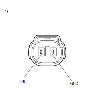
(b) Reconnect the A34 brake pedal stroke sensor assembly connector.

(c) Remove the brake master cylinder reservoir filler cap assembly.

(d) Make sure that there is no looseness at the locking part and the connecting part of the connector.

OK:

The connector is securely connected.

(e) Disconnect the A4 brake fluid level warning switch (brake booster with master cylinder assembly) connector.

(f) Check both the connector case and the terminals for deformation and corrosion.

OK:

No deformation or corrosion.

(g) Measure the resistance according to the value(s) in the table below.

HINT:

A float is located inside the brake master cylinder reservoir assembly (brake booster with master cylinder assembly). Its position changes according to the level of brake fluid.

Standard Resistance:

Tester Connection

Condition

Specified Condition

2 (LBL) - 1 (GND)

Brake fluid level warning switch (brake booster with master cylinder assembly) off (float up)

1.84 to 2.16 kΩ

2 (LBL) - 1 (GND)

Brake fluid level warning switch (brake booster with master cylinder assembly) on (float down)

Below 1 Ω

(Brake fluid level is low)

(h) If there are no problems after completing the preceding inspection, adjust the brake fluid to the MAX level with the power switch on (IG).

NG

REPLACE BRAKE BOOSTER WITH MASTER CYLINDER ASSEMBLY

OK

3.

CHECK HARNESS AND CONNECTOR (BRAKE BOOSTER WITH MASTER CYLINDER ASSEMBLY - BRAKE FLUID LEVEL WARNING SWITCH (BRAKE BOOSTER WITH MASTER CYLINDER ASSEMBLY))

(a) Turn the power switch off.

(b) Make sure that there is no looseness at the locking part and the connecting part of the connector.

OK:

The connector is securely connected.

(c) Disconnect the A35 skid control ECU (brake booster with master cylinder assembly) connector.

(d) Check both the connector case and the terminals for deformation and corrosion.

OK:

No deformation or corrosion.

(e) Measure the resistance according to the value(s) in the table below.

Standard Resistance:

Tester Connection

Condition

Specified Condition

A35-16 (LBL) - A4-2 (LBL)

Always

Below 1 Ω

A35-16 (LBL) or A4-2 (LBL) - Body ground

Always

10 kΩ or higher

A4-1 (GND) - Body ground

Always

Below 1 Ω

NG

REPAIR OR REPLACE HARNESS OR CONNECTOR

OK

4.

CHECK BRAKE DISC

(a) Reconnect the A35 skid control ECU (brake booster with master cylinder assembly) connector.

(b) Reconnect the A4 brake fluid level warning switch (brake booster with master cylinder assembly) connector.

(c) Disconnect the A34 brake pedal stroke sensor assembly connector.

(d) Perform a road test according to Freeze Frame Data or customer problem analysis. While driving, check for abnormal brake pedal vibration caused by brake discs that are worn or have excess runout.

OK:

Brake pedal does not vibrate during braking.

HINT:

  • An unevenly worn disc may vibrate the caliper pistons and cause fluctuations in brake line pressure, triggering a malfunction detection condition.
  • The brake pedal does not kick back due to caliper piston vibration during electronically controlled brake system control.
  • If the brake pedal stroke sensor assembly connector is disconnected, the fail-safe function will prohibit electronically controlled brake system control.
  • The Active Test does not prohibit electronically controlled brake system control when the vehicle is being driven, so disconnect the brake pedal stroke sensor assembly connector before continuing with inspection.
  • Uneven disc wear can be checked by measuring the disc thickness variation.

    for Front Brake: Click here

    for Rear Brake: Click here

NG

REPLACE BRAKE DISC

OK

5.

RECONFIRM DTC

(a) Turn the power switch off.

(b) Reconnect the A34 brake pedal stroke sensor assembly connector.

(c) Clear the DTCs.

Click here

Chassis > ABS/VSC/TRAC > Clear DTCs

(d) Turn the power switch off.

(e) Turn the power switch on (READY).

(f) Perform a road test.

(g) Check if the same DTC is output.

Click here

Chassis > ABS/VSC/TRAC > Trouble Codes

Result

Proceed to

DTC C120F is not output.

A

DTC C120F is output.

B

A

USE SIMULATION METHOD TO CHECK

B

REPLACE BRAKE BOOSTER WITH MASTER CYLINDER ASSEMBLY

    Accumulator Pressure Sensor Stuck (C14D5)

    Open Circuit in ABS Motor Relay Circuit (C146C,C146D)

    See More:

    Toyota Avalon Service & Repair Manual > Antenna Cord: Components
    COMPONENTS ILLUSTRATION *1 CENTER INSTRUMENT CLUSTER FINISH PANEL SUB-ASSEMBLY *2 CONSOLE BOX POCKET SUB-ASSEMBLY *3 FRONT CONSOLE UPPER PANEL GARNISH *4 LOWER INSTRUMENT PANEL FINISH PANEL LH *5 LOWER INSTRUMENT PANEL FINISH PANEL RH - - ILLUSTRATION *A w/o Navigation System *B w/ Navigation System ...

    Toyota Avalon Owners Manual

    Toyota Avalon Service & Repair Manual

    © 2024 Copyright www.tavalon.net
    0.0142