DESCRIPTION The ABS motor relay is built into the brake booster with master cylinder assembly.
During
ABS, TRAC, VSC, brake hold, secondary collision brake or brake assist
operation, the skid control ECU (brake booster with master cylinder
assembly) turns on the ABS motor relay to run the pump motor in the
brake actuator assembly. When any DTC related to
the ABS motor is stored, the IC built into the skid control ECU (brake
booster with master cylinder assembly) operates in fail-safe mode. When
the supplied voltage to the BM terminal of the ABS motor relay is
excessively low due to an auxiliary battery or charging circuit
malfunction, DTC C146C and/or C146D is stored. |
DTC No. | Detection Item |
INF Code | DTC Detection Condition |
Trouble Area | MIL |
Note | | C146C |
Open Circuit in ABS Motor Relay Circuit |
612 | When operation of the ABS motor is requested, the ABS motor voltage is less than 7.6 V for 0.2 seconds or more. |
- Wire harness or connector
- Skid control ECU (brake booster with master cylinder assembly)
- Brake actuator assembly
| Comes on |
- INF Code 612: SAE Code C052E
- ABS DTC
| | C146D |
Short Circuit in ABS Motor Relay Circuit |
613 | A short in the ABS motor relay drive circuit is detected for 4 seconds or more. |
- Wire harness or connector
- Skid control ECU (brake booster with master cylinder assembly)
- Brake actuator assembly
| Comes on |
- INF Code 613: SAE Code C052D (Case 1)
- ABS DTC
| MONITOR DESCRIPTION
The skid control ECU (brake booster with master cylinder assembly) monitors the voltage of the ABS motor.
When
the ABS motor relay is instructed to be on and the voltage of the ABS
motor is within the range of an open circuit malfunction, or when the
ABS motor is instructed to be off and the voltage of the ABS motor is
within the range of a short circuit malfunction, an open circuit or
short circuit is judged respectively and the MIL is illuminated and a
DTC is stored. MONITOR STRATEGY |
Related DTCs | C052D (Case 1): ABS pump motor circuit high
C052E: ABS pump motor open circuit | |
Required Sensors/Components(Main) | Brake actuator assembly | |
Required Sensors/Components(Related) | Skid control ECU (brake booster with master cylinder assembly)
Brake actuator assembly | | Frequency of Operation |
Continuous | | Duration |
0.2 seconds: C052E 4 seconds: C052D (Case 1) | |
MIL Operation | Immediately | |
Sequence of Operation | None | TYPICAL ENABLING CONDITIONS All |
Monitor runs whenever the following DTCs are not stored |
None | C052E |
Either of the following conditions is met |
A or B | | A. Both of the following conditions are met |
- | | ABS pump motor voltage is 7.607 V or more experience |
Not met | | Command to ABS motor relay |
On | | B. All of the following conditions are met |
- | | ABS pump motor voltage is 7.607 V or more experience |
Met | | Command to ABS motor relay |
On | | Power supply for ABS motor |
Higher than 9.13 V | C052D (Case 1) |
Command to ABS motor relay | Off | TYPICAL MALFUNCTION THRESHOLDS C052E |
ABS pump motor voltage | Less than 7.607 V | C052D (Case 1) |
ABS pump motor voltage | 7.607 V or more, and less than 18.57 V | COMPONENT OPERATING RANGE C052E |
Both of the following conditions are met |
- | | Command to ABS motor relay |
On | | ABS pump motor voltage |
7.607 V or more | C052D (Case 1) |
ABS pump motor voltage | Less than 7.607 V, or 18.57 V or more | CONFIRMATION DRIVING PATTERN
- Connect the Techstream to the DLC3.
- Turn the power switch on (IG).
- Turn the Techstream on.
- Clear the DTCs (even if no DTCs are stored, perform the clear DTC procedure).
- Turn the power switch off.
- Turn the power switch on (IG).
- Turn the Techstream on.
- Wait 4 seconds.
- Enter the following menus: Chassis / ABS/VSC/TRAC / Trouble Codes.
- Read the DTCs.
HINT:
- If a DTC is output, the system is malfunctioning.
- If a DTC is not output, perform the following procedure.
- If the DTCs are not output, perform a universal trip and check for permanent DTCs.
Click here 
HINT:
- If a permanent DTC is output, the system is malfunctioning.
- If no permanent DTCs are output, the system is normal.
WIRING DIAGRAM Refer to DTC C1427. Click here
CAUTION / NOTICE / HINT
NOTICE:
- After replacing the skid control ECU (brake booster with master cylinder
assembly), perform linear solenoid valve offset learning, ABS holding
solenoid valve learning, yaw rate and acceleration sensor zero point
calibration and system information memorization after performing "Reset
Memory".
Click here
- Inspect the fuses for circuits related to this system before performing the following procedure.
HINT: When
DTCs C1241 and/or C1417 are output together with C146C and/or C146D,
inspect and repair the trouble areas indicated by C1241 and/or C1417
first. for C1241: Click here for C1417: Click here
PROCEDURE
| 1. |
CHECK HARNESS AND CONNECTOR (BM TERMINAL) |
| (a) Make sure that there is no looseness at the locking part and the connecting part of the connector.
OK: The connector is securely connected. |
 |
|
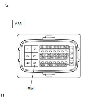
*a | Front view of wire harness connector
(to Skid Control ECU (Brake Booster with Master Cylinder Assembly)) | | |
(b) Disconnect the A35 skid control ECU (brake booster with master cylinder assembly) connector.
(c) Check both the connector case and the terminals for deformation and corrosion.
OK: No deformation or corrosion. (d) Measure the voltage according to the value(s) in the table below.
Standard Voltage: |
Tester Connection | Condition |
Specified Condition | |
A35-41 (BM) - Body ground |
Always | 11 to 14 V |
| NG |
 | REPAIR OR REPLACE HARNESS OR CONNECTOR (BM CIRCUIT) |
|
OK |
 | |
| 2. |
CHECK HARNESS AND CONNECTOR (BRAKE BOOSTER WITH MASTER CYLINDER ASSEMBLY - BRAKE ACTUATOR ASSEMBLY) |
(a) Make sure that there is no looseness at the locking part and the connecting part of the connector.
OK: The connector is securely connected. (b) Disconnect the A39 brake actuator assembly connector.
(c) Check both the connector case and the terminals for deformation and corrosion.
OK: No deformation or corrosion. (d) Measure the resistance according to the value(s) in the table below.
Standard Resistance: |
Tester Connection | Condition |
Specified Condition | |
A35-40 (+BM) - A39-10 (+BM) |
Always | Below 1 Ω | |
A35-40 (+BM) or A39-10 (+BM) - Body ground |
Always | 10 kΩ or higher |
| NG |
| REPAIR OR REPLACE HARNESS OR CONNECTOR |
|
OK | |
| |
| 3. |
CHECK HARNESS AND CONNECTOR (GND TERMINAL) |
| (a) Measure the resistance according to the value(s) in the table below.
Standard Resistance: |
Tester Connection | Condition |
Specified Condition | |
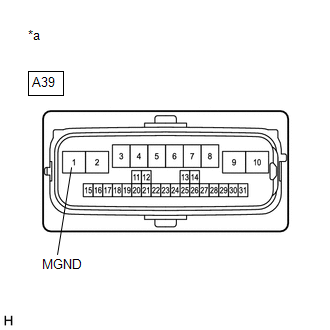
A39-1 (MGND) - Body ground |
Always | Below 1 Ω | |
 |
|
*a | Front view of wire harness connector
(to Brake Actuator Assembly) | | |
| NG |
| REPAIR OR REPLACE HARNESS OR CONNECTOR (GND CIRCUIT) |
|
OK | |
| |
(a) Reconnect the A35 skid control ECU (brake booster with master cylinder assembly) connector.
(b) Reconnect the A39 brake actuator assembly connector. (c) Clear the DTCs.
Click here Chassis > ABS/VSC/TRAC > Clear DTCs
(d) Turn the power switch off. (e) Turn the power switch on (READY).
(f) Perform a road test. (g) Check if the same DTC is output. Click here
Chassis > ABS/VSC/TRAC > Trouble Codes
| Result |
Proceed to | | DTCs C146C and C146D are not output. |
A | | DTCs C146C and/or C146D are output. |
B |
HINT:
- If a speed signal of 20 km/h (12 mph) or more is sent to the skid
control ECU (brake booster with master cylinder assembly) with the power
switch on (IG) and the stop light switch assembly off, the ECU performs
self-diagnosis of the motor and solenoid circuits.
- If the normal system code is output (no DTCs are output), slightly
jiggle the connectors, wire harness, and fuses of the skid control ECU
(brake booster with master cylinder assembly).
- If any DTCs are output while jiggling a connector or wire harness from
the skid control ECU (brake booster with master cylinder assembly),
inspect and repair the connector or wire harness.
- The DTCs were probably output due to a bad connection of the connector terminal.
| A |
| USE SIMULATION METHOD TO CHECK |
| B |
| REPLACE BRAKE BOOSTER WITH MASTER CYLINDER ASSEMBLY | | 

