DESCRIPTION |
DTC No. | Detection Item |
INF Code | DTC Detection Condition |
Trouble Area | MIL |
Note | | C1202 |
Master Reservoir Level Malfunction |
1126 | Either of the following is detected:
- The brake fluid level warning switch signal circuit is open for a certain period of time.
- The reservoir level is low for a certain period of time.
|
- Open or short in brake fluid level warning switch (brake booster with master cylinder assembly)
- Brake fluid leaks
- Open or short in wire harness
- Low brake fluid
- Skid control ECU (brake booster with master cylinder assembly)
| Comes on |
- INF Code 1126: SAE Code C1202
- Electronically controlled brake system DTC
HINT: DTC C1202 (INF code 1126) is cleared when the conditions return to normal. | MONITOR DESCRIPTION
When
the power switch is on (IG) and the fluid level warning switch (brake
booster with master cylinder assembly) is on for a certain amount of
time, the skid control ECU (brake booster with master cylinder assembly)
judges that the brake fluid level in the reservoir is low and
illuminates the MIL and stores this DTC. MONITOR STRATEGY |
Related DTCs | C1202: Brake master cylinder reservoir assembly level too low | |
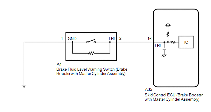
Required Sensors/Components(Main) | Brake fluid level warning switch (brake booster with master cylinder assembly)
Skid control ECU (brake booster with master cylinder assembly) | |
Required Sensors/Components(Related) | - | |
Frequency of Operation | Continuous | |
Duration | 20 seconds | | MIL Operation |
Immediately | | Sequence of Operation |
None | TYPICAL ENABLING CONDITIONS |
Monitor runs whenever the following DTCs are not stored |
None | | Power switch | On (IG) | TYPICAL MALFUNCTION THRESHOLDS |
One of the following conditions is met | - | |
Brake fluid level warning switch state |
On | | Brake fluid level warning switch state |
Open circuit | | Serial communication with IC |
Invalid | COMPONENT OPERATING RANGE |
All of the following conditions are met | - | |
Power switch | On (IG) | | Brake fluid level warning switch state |
Off | | Serial communication with IC |
Valid | CONFIRMATION DRIVING PATTERN
- Connect the Techstream to the DLC3.
- Turn the power switch on (IG).
- Turn the Techstream on.
- Clear the DTCs (even if no DTCs are stored, perform the clear DTC procedure).
- Turn the power switch off.
- Turn the power switch on (IG).
- Turn the Techstream on.
- Wait 20 seconds.
- Enter the following menus: Chassis / ABS/VSC/TRAC / Trouble Codes.
- Read the DTCs.
HINT:
- If a DTC is output, the system is malfunctioning.
- If a DTC is not output, perform the following procedure.
- If the DTCs are not output, perform a universal trip and check for permanent DTCs.
Click here 
HINT:
- If a permanent DTC is output, the system is malfunctioning.
- If no permanent DTCs are output, the system is normal.
WIRING DIAGRAM
 CAUTION / NOTICE / HINT
NOTICE: After
replacing the skid control ECU (brake booster with master cylinder
assembly), perform linear solenoid valve offset learning, ABS holding
solenoid valve learning, yaw rate and acceleration sensor zero point
calibration and system information memorization after performing "Reset
Memory". Click here PROCEDURE
(a) Clear the DTCs. Click here
Chassis > ABS/VSC/TRAC > Clear DTCs
(b) Turn the power switch off. (c) Turn the power switch on (IG).
(d) Check if the same DTC is output. Click here
Chassis > ABS/VSC/TRAC > Trouble Codes
| Result |
Proceed to | | DTC C1202 is output. |
A | | DTC C120F is output with DTC C1202. |
B |
| B |
 | GO TO DTC (C120F) |
|
A |
 | |
| 2. |
CHECK BRAKE FLUID LEVEL | (a) Check that the brake fluid level is sufficient.
HINT: If the fluid level is low, check for fluid leaks, and repair as necessary.
(1)
Check for brake fluid leaks (connection between the brake booster pump
assembly, brake master cylinder reservoir assembly (brake booster with
master cylinder assembly), brake booster with master cylinder assembly,
and wheel cylinders). HINT: If no leaks exist, add and adjust fluid using the Techstream.
Click here (2) Check the thickness of the brake pad lining.
for Front Brake: Click here for Rear Brake: Click here
HINT: If the thickness is less than the standard, replace the brake pads with new ones.
(b)
Check that there are no leaks from the connections between the brake
booster pump assembly and brake booster with master cylinder assembly. HINT:
As a visual check is very difficult, perform the check with the following procedure.
(1) Bleed the air from the brake system. Click here
(2) Turn the power switch off. (3) Disconnect the A34 brake pedal stroke sensor assembly connector.
(4) Select the Data List on the Techstream. Click here
Chassis > ABS/VSC/TRAC > Data List
|
Tester Display | Measurement Item |
Range | Normal Condition |
Diagnostic Note | |
MT Voltage Value | MT voltage value |
Min.: 0.00 V, Max.: 20.00 V |
Pump motor off: 0.00 V Pump motor on: 12.00 V |
- | | Accumulator Pressure |
Accumulator pressure output value |
Min.: 0.00 MPa, Max.: 24.48 MPa |
15.00 to 21.00 MPa (Pressure stable and pump motor stopped) |
When
brake fluid is stored in the accumulator: Accumulator pressure changes
in accordance with volume of fluid stored in the accumulator | Chassis > ABS/VSC/TRAC > Data List
|
Tester Display | | MT Voltage Value | |
Accumulator Pressure | (5) Depress the brake pedal several times to operate the pump motor, then wait until it stops.
(6)
After the pump motor stops, wait for 30 seconds, then check the drop in
the accumulator pressure sensor output value and the state of the pump
motor. | Result |
Proceed to | | The
drop in the accumulator pressure sensor output value is less than 2.50
MPa 30 seconds after the pump motor stops, and the pump motor does not
operate within 30 seconds after the pump motor stops. |
A | | The
drop in the accumulator pressure sensor output value is 2.50 MPa or
more 30 seconds after the pump motor stops, or the pump motor operates
within 30 seconds after the pump motor stops. |
B |
| B |
| CHECK AND REPAIR BRAKE FLUID LEAKS OR ADD FLUID |
|
A | |
| |
| 3. |
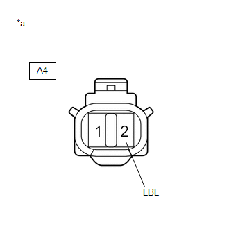
INSPECT BRAKE BOOSTER WITH MASTER CYLINDER ASSEMBLY (BRAKE FLUID LEVEL WARNING SWITCH) |
| (a) Turn the power switch off. |
 |
|
*a | Component without harness connected
(Brake Fluid Level Warning Switch (Brake Booster with Master Cylinder Assembly)) | | |
(b) Reconnect the A34 brake pedal stroke sensor assembly connector. (c) Remove the brake master cylinder reservoir filler cap assembly.
(d) Make sure that there is no looseness at the locking part and the connecting part of the connector.
OK: The connector is securely connected. (e) Disconnect the A4 brake fluid level warning switch (brake booster with master cylinder assembly) connector.
(f) Check both the connector case and the terminals for deformation and corrosion.
OK: No deformation or corrosion. (g) Measure the resistance according to the value(s) in the table below.
HINT: A
float is located inside the brake master cylinder reservoir assembly
(brake booster with master cylinder assembly). Its position changes
according to the level of brake fluid. Standard Resistance: |
Tester Connection | Condition |
Specified Condition | |
2 (LBL) - 1 (GND) | Brake fluid level warning switch (brake booster with master cylinder assembly) off (float up) |
1.84 to 2.16 kΩ | |
2 (LBL) - 1 (GND) | Brake fluid level warning switch (brake booster with master cylinder assembly) on (float down) |
Below 1 Ω (Brake fluid level is low) |
(h)
If there are no problems after completing the preceding inspection,
adjust the brake fluid to the MAX level with the power switch on (IG).
| NG |
| REPLACE BRAKE BOOSTER WITH MASTER CYLINDER ASSEMBLY |
|
OK | |
| |
| 4. |
CHECK
HARNESS AND CONNECTOR (BRAKE BOOSTER WITH MASTER CYLINDER ASSEMBLY -
BRAKE FLUID LEVEL WARNING SWITCH (BRAKE BOOSTER WITH MASTER CYLINDER
ASSEMBLY)) | (a) Make sure that there is no looseness at the locking part and the connecting part of the connector.
OK: The connector is securely connected. (b) Disconnect the A35 skid control ECU (brake booster with master cylinder assembly) connector.
(c) Check both the connector case and the terminals for deformation and corrosion.
OK: No deformation or corrosion. (d) Measure the resistance according to the value(s) in the table below.
Standard Resistance: |
Tester Connection | Condition |
Specified Condition | |
A35-16 (LBL) - A4-2 (LBL) |
Always | Below 1 Ω | |
A35-16 (LBL) or A4-2 (LBL) - Body ground |
Always | 10 kΩ or higher | |
A4-1 (GND) - Body ground |
Always | Below 1 Ω |
| NG |
| REPAIR OR REPLACE HARNESS OR CONNECTOR |
|
OK | |
| |
| 5. |
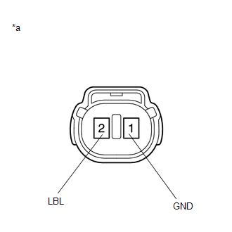
INSPECT BRAKE BOOSTER WITH MASTER CYLINDER ASSEMBLY (SWITCH INPUT) |
| (a) Reconnect the A35 skid control ECU (brake booster with master cylinder assembly) connector. |
 |
|
*a | Front view of wire harness connector
(to Brake Fluid Level Warning Switch (Brake Booster with Master Cylinder Assembly)) | | |
(b) Turn the power switch on (IG). (c) Measure the voltage according to the value(s) in the table below.
Standard Voltage: |
Tester Connection | Condition |
Specified Condition | |
A4-2 (LBL) - Body ground |
Power switch on (IG) |
11 to 14 V |
| NG |
| REPLACE BRAKE BOOSTER WITH MASTER CYLINDER ASSEMBLY |
|
OK | |
| |
(a) Turn the power switch off.
(b) Reconnect the A4 brake fluid level warning switch (brake booster with master cylinder assembly) connector.
(c) Clear the DTCs. Click here Chassis > ABS/VSC/TRAC > Clear DTCs
(d) Turn the power switch off. (e) Turn the power switch on (READY).
(f) Perform a road test. (g) Check if the same DTC is output. Click here
Chassis > ABS/VSC/TRAC > Trouble Codes
| Result |
Proceed to | | DTC C1202 is not output. |
A | | DTC C1202 is output. |
B |
| A |
| USE SIMULATION METHOD TO CHECK |
| B |
| REPLACE BRAKE BOOSTER WITH MASTER CYLINDER ASSEMBLY | | 

