DESCRIPTION The linear
solenoids SLA and SLR control the regulator based on signals from the
skid control ECU (brake booster with master cylinder assembly) and
produce servo pressure in accordance with the vehicle condition. When
the system is normal, the switching solenoid SGH is opened to allow
brake fluid to flow to the stroke simulator when the brake pedal is
depressed. When the system is abnormal, the switching solenoid SGH
closes to prevent the flow of brake fluid. When
the system is normal, the switching solenoid SSA is closed. When the
system is abnormal, the switching solenoid SSA is opened to allow fluid
to flow to the brake master cylinder reservoir assembly.
HINT:
- If the supply voltage decreases, a drop in current may cause DTCs to be stored.
- DTC C1225 indicates a malfunction related to solenoid SSA, and DTC C1226 indicates a malfunction related to solenoid SGH.
|
DTC No. | Detection Item |
INF Code | DTC Detection Condition |
Trouble Area | MIL |
Note | | C1211 |
SLA Linear Solenoid | 21
22 23 24 25 26 |
- INF Code: 21
- Overcurrent is detected in the solenoid for 0.05 seconds or more.
- INF Code: 22
- An open is detected in the solenoid for 0.05 seconds or more.
- INF Code: 23
- An excessive current is detected in the solenoid for 0.05 seconds or more.
- INF Code: 24
- Current leakage is detected in the solenoid for 0.05 seconds or more.
- INF Code: 25
- A malfunction in the solenoid current monitoring circuit is detected for 0.05 seconds or more.
- INF Code: 26
- Insufficient current is detected in the solenoid for 0.05 seconds or more.
|
- INF Code: 21, 22, 24
- Brake booster with master cylinder assembly
- INF Code: 23
- Supply voltage reduced
- Brake booster with master cylinder assembly
- INF Code: 25, 26
- Brake booster with master cylinder assembly
| Comes on |
- INF Code 21: SAE Code C13C3 (Case 4)
- INF Code 22: SAE Code C13C2 (Case 3)
- INF Code 23: SAE Code C13C3 (Case 1 and 2)
- INF Code 24: SAE Code C13C3 (Case 3)
- INF Code 25: SAE Code C13C1
- INF Code 26: SAE Code C13C2 (Case 1 and 2)
- Electronically controlled brake system DTC
| | C1212 |
SLR Linear Solenoid | 31
32 33 34 35 36 |
- INF Code: 31
- Overcurrent is detected in the solenoid for 0.05 seconds or more.
- INF Code: 32
- An open is detected in the solenoid for 0.05 seconds or more.
- INF Code: 33
- An excessive current is detected in the solenoid for 0.05 seconds or more.
- INF Code: 34
- Current leakage is detected in the solenoid for 0.05 seconds or more.
- INF Code: 35
- A malfunction in the solenoid current monitoring circuit is detected for 0.05 seconds or more.
- INF Code: 36
- Insufficient current is detected in the solenoid for 0.05 seconds or more.
|
- INF Code: 31, 32, 34
- Brake booster with master cylinder assembly
- INF Code: 33
- Supply voltage reduced
- Brake booster with master cylinder assembly
- INF Code: 35, 36
- Brake booster with master cylinder assembly
| Comes on |
- INF Code 31: SAE Code C13CC (Case 4)
- INF Code 32: SAE Code C13CB (Case 3)
- INF Code 33: SAE Code C13CC (Case 1 and 2)
- INF Code 34: SAE Code C13CC (Case 3)
- INF Code 35: SAE Code C13CA
- INF Code 36: SAE Code C13CB (Case 1 and 2)
- Electronically controlled brake system DTC
| | C1225 |
SA1 Solenoid Circuit |
41 42 43 44 45 46 |
- INF Code: 41
- Overcurrent is detected in SSA for 0.05 seconds or more.
- INF Code: 42
- An open is detected in SSA for 0.05 seconds or more.
- INF Code: 43
- Monitoring value of SSA continues to be excessively higher than request value.
- INF Code: 44
- Current leakage is detected in SSA for 0.05 seconds or more.
- INF Code: 45
- A malfunction in the SSA current monitoring circuit is detected for 0.05 seconds or more.
- INF Code: 46
- Monitoring value of SSA continues to be excessively lower than request value.
|
- INF Code: 41, 42, 44
- Brake booster with master cylinder assembly
- INF Code: 43
- Supply voltage reduced
- Brake booster with master cylinder assembly
- INF Code: 45, 46
- Brake booster with master cylinder assembly
| Comes on |
- INF Code 41: SAE Code C14F4 (Case 4)
- INF Code 42: SAE Code C14F3 (Case 3)
- INF Code 43: SAE Code C14F4 (Case 1 and 2)
- INF Code 44: SAE Code C14F4 (Case 3)
- INF Code 45: SAE Code C14F2
- INF Code 46: SAE Code C14F3 (Case 1 and 2)
- Electronically controlled brake system DTC
| | C1226 |
SA2 Solenoid Circuit |
71 72 73 74 75 76 |
- INF Code: 71
- Overcurrent is detected in SGH for 0.05 seconds or more.
- INF Code: 72
- An open is detected in SGH for 0.05 seconds or more.
- INF Code: 73
- Monitoring value of SGH continues to be excessively higher than request value.
- INF Code: 74
- Current leakage is detected in SGH for 0.05 seconds or more.
- INF Code: 75
- A malfunction in the SGH current monitoring circuit is detected for 0.05 seconds or more.
- INF Code: 76
- Monitoring value of SGH continues to be excessively lower than request value.
|
- INF Code: 71, 72, 74
- Brake booster with master cylinder assembly
- INF Code: 73
- Supply voltage reduced
- Brake booster with master cylinder assembly
- INF Code: 75, 76
- Brake booster with master cylinder assembly
| Comes on |
- INF Code 71: SAE Code C14FD (Case 4)
- INF Code 72: SAE Code C14FC (Case 3)
- INF Code 73: SAE Code C14FD (Case 1 and 2)
- INF Code 74: SAE Code C14FD (Case 3)
- INF Code 75: SAE Code C14FB
- INF Code 76: SAE Code C14FC (Case 1 and 2)
- Electronically controlled brake system DTC
| MONITOR DESCRIPTION
The
skid control ECU (brake booster with master cylinder assembly) monitors
the drive voltage and current of the linear solenoids (SLA, SLR, SSA
and SGH). Based on the monitored information, if any of the following
abnormal conditions are detected, the MIL is illuminated and a DTC is
stored.
- A malfunction of the current monitor is detected.
- Based on the duty cycle, the monitored current value is considerably low.
- An open circuit is detected.
- Based on the duty cycle, the monitored current value is considerably high.
- A current leakage is detected.
- When the monitored current value increases to a value that is not possible when normal.
MONITOR STRATEGY |
Related DTCs | C13C1: Linear solenoid range/performance
C13C2 (Case 1): Linear solenoid circuit low C13C2 (Case 2): Linear solenoid circuit low
C13C2 (Case 3): Linear solenoid circuit low C13C3 (Case 1): Linear solenoid circuit high
C13C3 (Case 2): Linear solenoid circuit high C13C3 (Case 3): Linear solenoid circuit high
C13C3 (Case 4): Linear solenoid circuit high C13CA: Linear solenoid range/performance
C13CB (Case 1): Linear solenoid circuit low C13CB (Case 2): Linear solenoid circuit low
C13CB (Case 3): Linear solenoid circuit low C13CC (Case 1): Linear solenoid circuit high
C13CC (Case 2): Linear solenoid circuit high C13CC (Case 3): Linear solenoid circuit high
C13CC (Case 4): Linear solenoid circuit high C14F2: Linear solenoid range/performance
C14F3 (Case 1): Linear solenoid circuit low C14F3 (Case 2): Linear solenoid circuit low
C14F3 (Case 3): Linear solenoid circuit low C14F4 (Case 1): Linear solenoid circuit high
C14F4 (Case 2): Linear solenoid circuit high C14F4 (Case 3): Linear solenoid circuit high
C14F4 (Case 4): Linear solenoid circuit high C14FB: Linear solenoid range/performance
C14FC (Case 1): Linear solenoid circuit low C14FC (Case 2): Linear solenoid circuit low
C14FC (Case 3): Linear solenoid circuit low C14FD (Case 1): Linear solenoid circuit high
C14FD (Case 2): Linear solenoid circuit high C14FD (Case 3): Linear solenoid circuit high
C14FD (Case 4): Linear solenoid circuit high | |
Required Sensors/Components(Main) | Skid control ECU (brake booster with master cylinder assembly)
Brake actuator (brake booster with master cylinder assembly) | |
Required Sensors/Components(Related) | Skid control ECU (brake booster with master cylinder assembly)
Brake actuator (brake booster with master cylinder assembly) | |
Frequency of Operation | Continuous | |
Duration | 0.054
seconds: C13C1, C13C2 (Case 2), C13C2 (Case 3), C13C3 (Case 2), C13C3
(Case 3), C13C3 (Case 4), C13CA, C13CB (Case 2), C13CB (Case 3), C13CC
(Case 2), C13CC (Case 3), C13CC (Case 4), C14F2, C14F3 (Case 2), C14F3
(Case 3), C14F4 (Case 2), C14F4 (Case 3), C14F4 (Case 4), C14FB, C14FC
(Case 2), C14FC (Case 3), C14FD (Case 2), C14FD (Case 3) and C14FD (Case
4) 7 times: C14F3 (Case 1), C14F4 (Case 1), C14FC (Case 1) and C14FD (Case 1)
14 times: C13C2 (Case 1), C13C3 (Case 1), C13CB (Case 1) and C13CC (Case 1) | |
MIL Operation | Immediately | |
Sequence of Operation | None | TYPICAL ENABLING CONDITIONS C13C1, C13CA, C14F2 and C14FB |
Monitor runs whenever the following DTCs are not stored |
None | | Both of the following conditions are met |
- | | Serial communication with high side IC |
Valid | | Solenoid low side operating |
On | C13C2, C13CB, C14F3 and C14FC (Case 1) |
Monitor runs whenever the following DTCs are not stored |
None | | All of the following conditions are met |
- | | Power supply for linear solenoid |
Higher than 9.13 V | | Command to main relay |
On | | Main relay | On | |
Serial communication with high side IC | Valid | |
Solenoid low side operating | On | |
Current | Less than 2.3 A | |
Difference in present target current and previous target current |
0.2 A or less | | Output duty cycle |
Higher than 0% | | Difference in present power supply voltage for linear solenoid and previous power supply voltage for linear solenoid |
1 V or less | | Solenoid current correction coefficient learning |
Complete | | Current monitor |
Normal | C13C2, C13CB, C14F3 and C14FC (Case 2) |
Monitor runs whenever the following DTCs are not stored |
None | | All of the following conditions are met |
A, B, C, D, E, F, G, H, I and J | | A. Power supply for linear solenoid |
Higher than 9.13 V | | B. Command to main relay |
On | | C. Main relay | On | |
D. Serial communication with high side IC | Valid | |
E. Solenoid low side operating | On | |
F. Current | Less than 2.3 A | |
G. Difference in present target current and previous target current |
0.2 A or less | | H. Output duty cycle |
Higher than 0% | | I. Current monitor |
Normal | | J. Either of the following conditions is met |
- | | Difference in present power supply voltage for linear solenoid and previous power supply voltage for linear solenoid |
Higher than 1 V | | Solenoid current correction coefficient learning |
Not complete | C13C2, C13CB, C14F3 and C14FC (Case 3) |
Monitor runs whenever the following DTCs are not stored |
None | | All of the following conditions are met |
- | | Command to main relay |
On | | Main relay | On | |
Solenoid low side operating | On | |
Serial communication with high side IC | Valid | |
Output duty cycle | 0% | | Current monitor |
Normal | | Current | Less than 0.2 A | C13C3, C13CC, C14F4 and C14FD (Case 1) |
Monitor runs whenever the following DTCs are not stored |
None | | All of the following conditions are met |
- | | Power supply for linear solenoid |
Less than 16 V | | Serial communication with high side IC |
Valid | | Solenoid low side operating |
On | | Difference in present target current and previous target current |
0.2 A or less | | Difference in present power supply voltage for linear solenoid and previous power supply voltage for linear solenoid |
1 V or less | | Solenoid current correction coefficient learning |
Complete | | Current monitor | Normal | C13C3, C13CC, C14F4 and C14FD (Case 2) |
Monitor runs whenever the following DTCs are not stored |
None | | All of the following conditions are met |
A, B, C, D, E and F | | A. Power supply for linear solenoid |
Less than 16 V | | B. Serial communication with high side IC |
Valid | | C. Solenoid low side operating |
On | | D. Difference in present target current and previous target current |
0.2 A or less | | E. Current monitor |
Normal | | F. Either of the following conditions is met |
- | | Difference in present power supply voltage for linear solenoid and previous power supply voltage for linear solenoid |
Higher than 1 V | | Solenoid current correction coefficient learning |
Not complete | C13C3, C13CC, C14F4 and C14FD (Case 3) |
Monitor runs whenever the following DTCs are not stored |
None | | All of the following conditions are met |
- | | Solenoid low side operating |
On | | Output duty cycle | 0% | |
Current monitor | Normal | C13C3, C13CC, C14F4 and C14FD (Case 4) |
Monitor runs whenever the following DTCs are not stored |
None | | Both of the following conditions are met |
- | | Serial communication with high side IC |
Valid | | Current monitor power supply |
Higher than 1.09 V, and less than 1.24 V | TYPICAL MALFUNCTION THRESHOLDS C13C1 and C13CA |
One of the following conditions is met | A, B, C, D or E | |
A. Difference in monitor current (for solenoid control) and monitor current (for monitoring) |
Higher than 0.281 A | | B. Both of the following conditions are met |
- | | Current monitor value (for solenoid control) |
33 or less | | Current | Less than 2.3 A | |
C. Both of the following conditions are met | - | |
Current monitor value (for monitoring) | 33 or less | |
Current | Less than 2.3 A | |
D. Reference voltage for current monitor circuit | 1.24 V or more, or 1.09 V or less | |
E. AC/DC converter built into CPU standard voltage | 4.4 V or less | C14F2 and C14FB |
One of the following conditions is met | A, B, C, D or E | |
A. Difference in monitor current (for solenoid control) and monitor current (for monitoring) |
Higher than 0.294 A | | B. Both of the following conditions are met |
- | | Current monitor value (for solenoid control) |
33 or less | | Current | Less than 2.3 A | |
C. Both of the following conditions are met | - | |
Current monitor value (for monitoring) | 33 or less | |
Current | Less than 2.3 A | |
D. Reference voltage for current monitor circuit | 1.24 V or more, or 1.09 V or less | |
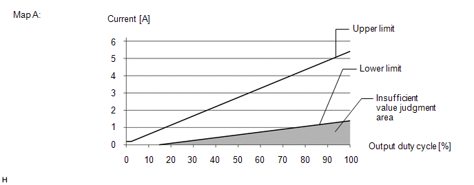
E. AC/DC converter built into CPU standard voltage | 4.4 V or less | C13C2, C13CB, C14F3 and C14FC (Case 1) |
Solenoid current to output duty cycle relationship | Within the insufficient value judgment area in the following Map A |
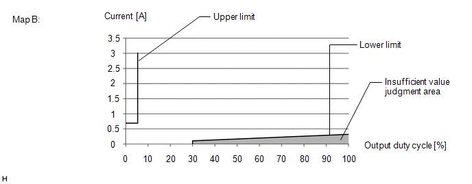
 C13C2, C13CB, C14F3 and C14FC (Case 2) C13C2, C13CB, C14F3 and C14FC (Case 2) |
Solenoid current to output duty cycle relationship | Within the insufficient value judgment area in the following Map B |
 C13C2, C13CB, C14F3 and C14FC (Case 3) C13C2, C13CB, C14F3 and C14FC (Case 3) |
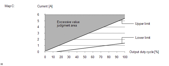
Solenoid high side voltage | Higher than 5.46 V | C13C3, C13CC, C14F4 and C14FD (Case 1) |
Solenoid current to output duty cycle relationship | Within the excessive value judgment area in the following Map C |
 C13C3, C13CC, C14F4 and C14FD (Case 2) C13C3, C13CC, C14F4 and C14FD (Case 2) |
Solenoid current to output duty cycle relationship | Within the excessive value judgment area in the following Map D |
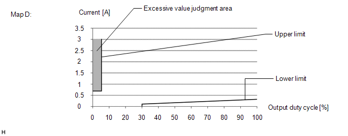 C13C3, C13CC, C14F4 and C14FD (Case 3) C13C3, C13CC, C14F4 and C14FD (Case 4) C13C3, C13CC, C14F4 and C14FD (Case 3) C13C3, C13CC, C14F4 and C14FD (Case 4) |
Current | Higher than 2.3 A | COMPONENT OPERATING RANGE C13C1 and C13CA |
All of the following conditions are met | - | |
Output duty cycle | Higher than 0% | |
Difference in monitor current (for solenoid control) and monitor current (for monitoring) |
Less than 0.281 A | | Current monitor value (for solenoid control) |
More than 33 | | Current monitor value (for monitoring) |
More than 33 | | Current | Less than 2.3 A | |
Reference voltage for current monitor circuit | Less than 1.24 V, and higher than 1.09 V | |
AC/DC converter built into CPU standard voltage | Higher than 4.4 V | C14F2 and C14FB |
All of the following conditions are met | - | |
Serial communication with high side IC |
Valid | | Solenoid low side operating |
On | | Difference in monitor current (for solenoid control) and monitor current (for monitoring) |
0.294 A or less | | Current monitor value (for solenoid control) |
More than 33 | | Current monitor value (for monitoring) |
More than 33 | | Current | Less than 2.3 A | |
Reference voltage for current monitor circuit | Less than 1.24 V, and higher than 1.09 V | |
AC/DC converter built into CPU standard voltage | Higher than 4.4 V | C13C2, C13CB, C14F3 and C14FC (Case 1 and 2) |
All of the following conditions are met | - | |
Power supply for linear solenoid | Higher than 9.13 V | |
Command to main relay | On | |
Main relay | On | | Serial communication with high side IC |
Valid | | Solenoid low side operating |
On | | Current | Less than 2.3 A | |
Difference in present target current and previous target current |
0.2 A or less | | Output duty cycle |
Higher than 0% | | Current monitor |
Normal | | Solenoid current to output duty cycle relationship |
Current is not below lower limit (Outside of the insufficient value judgment area in the following Map A) |
C13C2, C13CB, C14F3 and C14FC (Case 3) |
All of the following conditions are met | - | |
Main relay | On | | Solenoid low side operating |
On | | Serial communication with high side IC |
Valid | | Output duty cycle |
0% | | High side IC malfunction |
Not detected | | Solenoid high side voltage |
5.46 V or less | C13C3, C13CC, C14F4 and C14FD (Case 1 and 2) |
All of the following conditions are met | - | |
Power supply for linear solenoid | Less than 16 V | |
Serial communication with high side IC | Valid | |
Solenoid low side operating | On | |
Difference in present target current and previous target current |
0.2 A or less | | Current monitor |
Normal | | Output duty cycle |
Higher than 0% | | Solenoid current to output duty cycle relationship |
Current is not above upper limit (Outside of the excessive value judgment area in the following Map C) |
C13C3, C13CC, C14F4 and C14FD (Case 3) |
All of the following conditions are met | - | |
Main relay | On | | Solenoid low side operating |
On | | Output duty cycle | 0% | |
Current monitor | Normal | | Current |
Less than 0.15 A | C13C3, C13CC, C14F4 and C14FD (Case 4) |
All of the following conditions are met | - | |
Main relay | On | | Solenoid low side operating |
On | | Serial communication with high side IC |
Valid | | Output duty cycle |
Higher than 0% | | Current |
Less than 2.3 A | CONFIRMATION DRIVING PATTERN
- Connect the Techstream to the DLC3.
- Turn the power switch on (IG).
- Turn the Techstream on.
- Clear the DTCs (even if no DTCs are stored, perform the clear DTC procedure).
- Turn the power switch off.
- Turn the power switch on (IG).
- Turn the Techstream on.
- Depress the brake pedal 1 or more times.
- Enter the following menus: Chassis / ABS/VSC/TRAC / Trouble Codes.
- Read the DTCs.
HINT:
- If a DTC is output, the system is malfunctioning.
- If a DTC is not output, perform the following procedure.
- If the DTCs are not output, perform a universal trip and check for permanent DTCs.
Click here 
HINT:
- If a permanent DTC is output, the system is malfunctioning.
- If no permanent DTCs are output, the system is normal.
CAUTION / NOTICE / HINT NOTICE: After
replacing the skid control ECU (brake booster with master cylinder
assembly), perform linear solenoid valve offset learning, ABS holding
solenoid valve learning, yaw rate and acceleration sensor zero point
calibration and system information memorization after performing "Reset
Memory". Click here PROCEDURE
(a) Clear the DTCs. Click here
Chassis > ABS/VSC/TRAC > Clear DTCs
(b) Turn the power switch off. (c) Turn the power switch on (IG).
(d) Check if the same DTC is output. Click here
Chassis > ABS/VSC/TRAC > Trouble Codes
HINT: If a DTC for undervoltage is output, first troubleshoot the power source system.
| Result |
Proceed to | | DTCs C1211, C1212, C1225 and C1226 are not output. |
A | | A DTC related to low voltage is output. |
B | | DTCs C1211, C1212, C1225 and/or C1226 are output. |
C |
| A |
 | USE SIMULATION METHOD TO CHECK |
| B |
| REPAIR CIRCUITS INDICATED BY OUTPUT DTCS |
| C |
| REPLACE BRAKE BOOSTER WITH MASTER CYLINDER ASSEMBLY | |


