DESCRIPTION The skid
control ECU (brake booster with master cylinder assembly) controls
braking force according to the hybrid control system regenerative
braking force and provides the hydraulic pressure necessary for
operating the master cylinder and each wheel cylinder according to the
servo pressure sensor. DTCs may be stored if one of the following occurs:
- Brake fluid leaks.
- Wheel cylinder vibrates due to uneven wear of a brake disc.
- Foreign matter enters a solenoid valve.
- Line pressure drops during air bleeding.
- Brake pads are replaced.
- Rotors are replaced.
HINT:
When
replacing the brake pads, retracting the brake caliper pistons and
installing new brake pads will greatly increase the clearance between
the brake pads and brake discs. This will result in a significant
possibility of this DTC being stored the next time the brake pedal is
depressed. As this is not a malfunction, clear the DTC if it is stored
for this reason.
|
DTC No. | Detection Item |
INF Code | DTC Detection Condition |
Trouble Area | MIL |
Note | | C1214 |
Hydraulic Control System Malfunction |
431 432 436 438 440 441 442 |
- INF Code: 431
- Fluid pressure control performance degraded (high pressure).
- INF Code: 432
- Fluid pressure control performance degraded (low pressure).
- INF Code: 436
- SLA valve malfunction (stuck, etc.).
- INF Code: 438
- Malfunction in one of the two circuits (leakage, etc.).
- INF Code: 440
- SSA valve malfunction (stuck, etc.).
- INF Code: 441
- SGH valve malfunction (stuck, etc.).
- INF Code: 442
- Malfunction (leakage, etc.) detected in the ABS decrease pressure valve in the brake actuator assembly.
|
- INF Code: 431, 432, 436, 438, 440, 441
- Brake fluid leaks
- Uneven brake disc rotor wear
- Brake actuator (brake booster with master cylinder assembly)
- INF Code: 442
| Comes on |
- INF Code 431: SAE Code C13CD
- INF Code 432: SAE Code C13CE
- INF Code 436: SAE Code C139D
- INF Code 438: SAE Code C139A
- INF Code 440: SAE Code C14EE
- INF Code 441: SAE Code C14F7
- INF Code 442: SAE Code C1400
- Electronically controlled brake system DTC
| MONITOR DESCRIPTION C139A:
- After the power switch is turned off, the skid control ECU (brake
booster with master cylinder assembly) automatically performs a pressure
increase check to detect malfunctions that would be difficult to detect
during normal braking.
During the current trip when the vehicle is being
driven at a certain speed or more and the following sequence is met, if
the skid control ECU (brake booster with master cylinder assembly)
judges that there is a malfunction in a brake line in either of 2
systems, the MIL is illuminated and this DTC is stored.
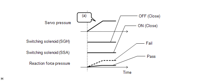
- When the switching solenoid (SSA) and switching solenoid (SGH) are
closed and the linear solenoid (SLA) is operating to increase servo
pressure, the reaction force pressure rises simultaneously. When there
is a malfunction in 1 system, the stroke amount increases because the
amount of increase in reaction force pressure is proportional to the
output piston stroke amount; therefore, when the reaction force pressure
is a specific value or more for a certain amount of time, the system
judges that there is a malfunction.
C139D:
- When the brake pedal is depressed, the skid control ECU (brake booster
with master cylinder assembly) monitors the servo pressure and increases
the servo pressure by driving the linear solenoid (SLA).
When the brake pedal is depressed, if the actual servo
pressure does not change even when the target servo pressure increases
for a certain amount of time, the skid control ECU (brake booster with
master cylinder assembly) judges that the linear solenoid (SLA) is stuck
closed (the pressure increase during initial braking is abnormal) and
illuminates the MIL and stores this DTC.
C13CD and C13CE:
- The skid control ECU (brake booster with master cylinder assembly)
monitors the relationship between the specified increase or decrease in
servo pressure and the target brake fluid pressure.
When the brake pedal is depressed and the relationship
between the servo pressure and the target brake fluid pressure is
outside of the normal range, the skid control ECU (brake booster with
master cylinder assembly) judges that the increasing pressure is
abnormal and illuminates the MIL and stores a DTC.
Furthermore,
when the brake pedal is released or while braking is being performed
and the relationship between the servo pressure and the target brake
fluid pressure is outside of the normal range, the skid control ECU
(brake booster with master cylinder assembly) judges that the decreasing
pressure is abnormal and illuminates the MIL and stores a DTC.
C1400:
- After the power switch is turned off, the skid control ECU (brake
booster with master cylinder assembly) automatically performs a pressure
increase check to detect malfunctions that would be difficult to detect
during normal braking.
During the current trip when the vehicle is being
driven at a certain speed or more and the following sequence is met, the
skid control ECU (brake booster with master cylinder assembly) judges
that the ABS reduction solenoid valve is leaking and illuminates the MIL
and stores this DTC.
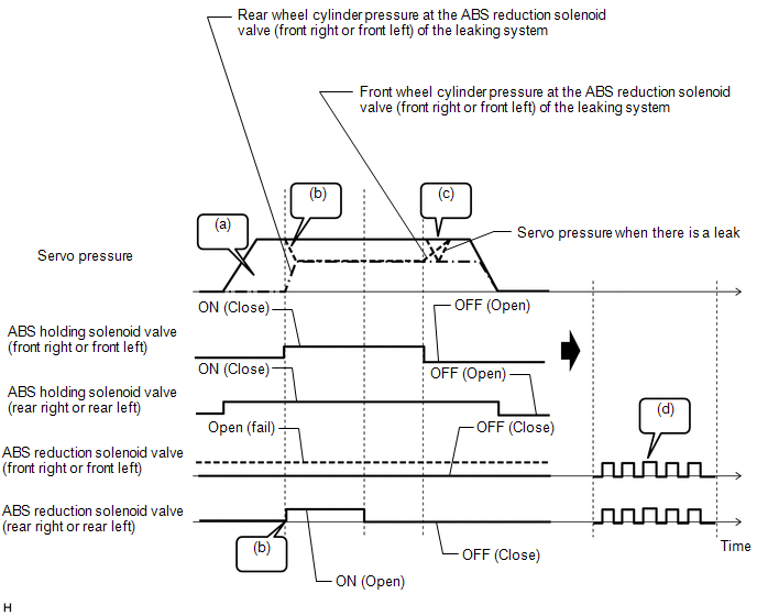
HINT:
Although
the following sequence is related to the front left and front right, an
identical sequence is performed to check for leaks in the rear left and
rear right.
- The brake fluid pressure at the front left and front right wheel
cylinders is equal to that of the brake booster with master cylinder
assembly. No brake fluid pressure is applied to the rear wheel
cylinders.
- The ABS holding solenoid valves of the 4 wheels are closed to isolate
the brake booster with master cylinder assembly and each wheel cylinder,
and the rear left and rear right ABS reduction solenoids are opened. At
this time, the pressure does not change if there is no leak; however,
if a front left or front right ABS reduction solenoid valve is leaking,
because both wheel cylinders of the system that is leaking (front right
and rear left, or front left and rear right) are connected, the pressure
of the front wheel cylinder of the leaking system falls lower than that
of the brake booster with master cylinder assembly.
- When the front right and front left ABS holding solenoid valves are
opened, because brake fluid flows from the brake booster with master
cylinder assembly to the leaking system, the servo pressure temporarily
drops. At this time, if the drop in servo pressure is at a specific
value or more and the servo pressure decreases at a specific value or
less, it is temporarily judged that there is a leak malfunction.
- In the case of (c), if the pressure temporarily drops (temporarily
judged as a leak malfunction), the ABS reduction solenoid valves are
opened and closed repeatedly to eliminate the leak.
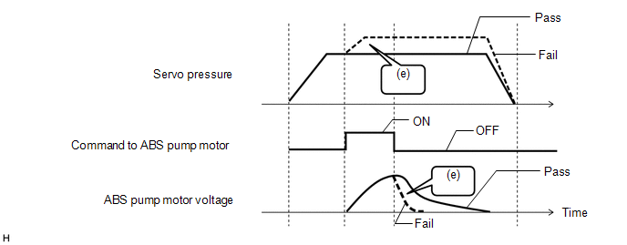
- Because the ABS reduction solenoid valve is leaking, brake fluid leaks
to the reservoir inside the brake actuator assembly, such as in the case
of (a). When the ABS pump motor is operated in this situation, brake
fluid in the reservoir is pumped to the brake booster with master
cylinder assembly and the servo pressure increases. As the increase in
servo pressure loads the ABS pump motor, a rapid voltage drop is
produced when the pump motor is stopped. Because of that, if the
increase in servo pressure when the ABS pump motor is operating is above
a specific value, and the time taken for the ABS pump motor voltage to
drop when the ABS pump motor stops operating is shorter than normal, it
is judged that there is a malfunction.
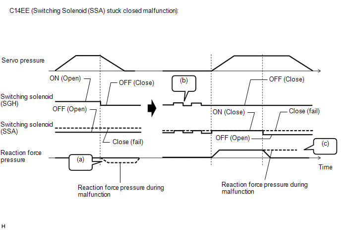
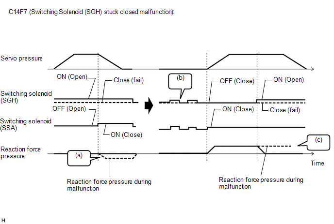
C14EE and C14F7:
- After the power switch is turned off, the skid control ECU (brake
booster with master cylinder assembly) automatically performs a pressure
increase check to detect malfunctions that would be difficult to detect
during normal braking.
During the current trip when the vehicle is being
driven at a certain speed or more and the following sequence is met, the
skid control ECU (brake booster with master cylinder assembly) judges
that the switching solenoid (SSA) or switching solenoid (SGH) is stuck
closed and illuminates the MIL and stores a DTC.
- When the linear solenoid (SLR) is being operated to reduce servo
pressure and the switching solenoid (SSA) and switching solenoid (SGH)
are both closed, when the output piston is released, the volume of the
reaction chamber expands, and because brake fluid is not introduced, a
negative pressure is created.
- In the case of (a), if the negative pressure does not change for a
certain amount of time, the skid control ECU (brake booster with master
cylinder assembly) repeatedly opens and closes the switching solenoid
(SSA) and switching solenoid (SGH).
- After (b) is performed, the linear solenoid (SLA) is operated to
increase servo pressure and the reaction force pressure rises. When the
switching solenoid (SSA) is instructed to be off (open) or the switching
solenoid (SGH) is instructed to be on (open) and there is a stuck
closed malfunction, because the reaction force pressure does not reduce,
when the reaction pressure exceeds a specific value for a certain
amount of time, the skid control ECU (brake booster with master cylinder
assembly) judges that there is a malfunction.
MONITOR STRATEGY |
Related DTCs | C139A: One hydraulic path fail C139D: Linear solenoid (SLA) stuck on
C13CD: Brake pressure too low C13CE: Brake pressure too high
C1400: ABS reduction solenoid leakage C14EE: Switching solenoid (SSA) stuck on
C14F7: Switching solenoid (SGH) stuck on | |
Required Sensors/Components(Main) | Skid control ECU (brake booster with master cylinder assembly)
Brake actuator (brake booster with master cylinder assembly) Brake actuator assembly | |
Required Sensors/Components(Related) | Speed sensor
Stop light switch assembly Skid control ECU (brake booster with master cylinder assembly)
Brake actuator (brake booster with master cylinder assembly) Brake pedal stroke sensor assembly | |
Frequency of Operation | Continuous: C139D, C13CD, C13CE
After power switch off: C139A, C1400, C14EE, C14F7 | |
Duration | Within
1 second: C139A (Case 1), C139A (Case 2), C139D (Case 1), C13CD (Case
1), C13CD (Case 2), C13CE (Case 1), C13CE (Case 2), C13CE (Case 3) and
C1400 1.002 seconds: C139D (Case 2) and C139D (Case 3) 1.5 seconds: (b) or (d) in the table of C14EE and C14F7 in Typical Malfunction Thresholds
6 seconds: (a) or (c) in the table of C14EE and C14F7 in Typical Malfunction Thresholds | |
MIL Operation | Immediately | |
Sequence of Operation | C1400:
- 1. Brake actuator assembly
- 2. Brake actuator (brake booster with master cylinder assembly), brake actuator assembly
| TYPICAL ENABLING CONDITIONS C139A
|
*: Electric Parking Brake System
| | Monitor runs whenever the following DTCs are not stored |
C0501, C0507, C050D, C0513 (Speed sensor range/performance) C0502, C0508, C050E, C0514 (Speed sensor circuit low)
C0503, C0509, C050F, C0515 (Speed sensor circuit high) C0504, C050A, C0510, C0516 (Speed sensor intermittent/erratic)
C051C (Case 1) (Acceleration sensor range/performance) C051C (Case 2) (Acceleration sensor range/performance)
C051C (Case 3) (Acceleration sensor range/performance) C051C (Case 4) (Acceleration sensor range/performance)
C051E (Acceleration sensor intermittent/erratic) C0520 (Case 1) (Acceleration sensor 2 out of range)
C0520 (Case 2) (Acceleration sensor 1 and acceleration sensor 2 out of range)
C0520 (Case 3) (Acceleration sensor internal malfunction) C052B (ABS pump motor range/performance)
C052D (ABS pump motor circuit high) C052E (ABS pump motor open circuit)
C0562 (Brake pedal stroke sensor assembly voltage circuit/open)
C0594 (Pump motor performance) C0597 (EEPROM malfunction)
C0597 (Lost communication) C0597 (CPU malfunction) C0597 (IC malfunction)
C1202 (Brake master cylinder reservoir assembly level too low)
C120F (Brake fluid level warning switch open circuit) C121D (Pump motor open circuit)
C121E (Pump motor circuit high) C123B (IG1 circuit low)
C123E (IG2 circuit low) C1240 (Yaw rate and acceleration sensor incorrect)
C1241 (Brake system voltage circuit low) C1241 (Speed sensor voltage circuit low)
C124A (CAN communication identification signal) C124B (Brake pedal stroke sensor assembly invalid data)
C1256 (Accumulator pressure too low) C12A6, C12BC, C12D2, C12E8 (ABS holding solenoid range/performance)
C12A7, C12BD, C12D3, C12E9 (ABS holding solenoid circuit low) C12A8, C12BE, C12D4, C12EA (ABS holding solenoid circuit high)
C12B2, C12C8, C12DE, C12F4 (ABS reduction solenoid circuit low)
C12B3, C12C9, C12DF, C12F5 (ABS reduction solenoid circuit high)
C12FA (Main relay circuit low) C12FB (Main relay circuit high)
C1336 (Acceleration sensor exceeded learning limit) C1345 (Linear solenoid open current learning not complete)
C1349 (ABS holding solenoid open current learning not complete)
C1392 (Brake pedal stroke sensor learning not complete) C139D (Linear solenoid (SLA) stuck on)
C13C1, C13CA, C14F2, C14FB (Linear solenoid range/performance)
C13C2, C13CB, C14F3, C14FC (Linear solenoid circuit low) C13C3, C13CC, C14F4, C14FD (Linear solenoid circuit high)
C13CD (Brake pressure too low) C13CE (Brake pressure too high)
C1400 (ABS reduction solenoid leakage) C140B, C140C, C140D, C140E (2 wheel speed sensors malfunction)
C1417 (Brake system voltage circuit high) C1427 (ABS pump motor stuck)
C1451 (High pressure hydraulic tube air bleeding not complete)
C146E (ABS solenoid power supply relay circuit low) C146F (ABS solenoid power supply relay circuit high)
C14B0 (Reaction force pressure sensor voltage circuit check) C14B1 (Reaction force pressure sensor lost communication)
C14B2 (Reaction force pressure sensor internal malfunction) C14B3 (Reaction force pressure sensor exceeded learning limit)
C14B4 (Reaction force pressure sensor intermittent/erratic) C14B5 (Reaction force pressure sensor invalid data)
C14B6 (Brake stroke/reaction force pressure correlation) C14C0 (Servo pressure sensor voltage circuit check)
C14C1 (Servo pressure sensor lost communication) C14C2 (Servo pressure sensor internal malfunction)
C14C3 (Servo pressure sensor exceeded learning limit) C14C4 (Servo pressure sensor intermittent/erratic)
C14C5 (Servo pressure sensor invalid data) C14D0 (Accumulator pressure sensor voltage circuit check)
C14D1 (Accumulator pressure sensor lost communication) C14D2 (Accumulator pressure sensor internal malfunction)
C14D3 (Accumulator pressure sensor intermittent/erratic) C14D4 (Case 1) (Accumulator pressure sensor invalid data)
C14D4 (Case 2) (Accumulator pressure sensor intermittent) C14D5 (Accumulator pressure sensor stuck)
C14D7 (Acceleration sensor voltage circuit/open) C14DB (ABS solenoid power supply voltage circuit low)
C14DE (Main relay voltage circuit low) C14DF (Main relay voltage circuit high)
C14E1, C14E4, C14E7, C14EA (Case 1) (Speed sensor voltage circuit low)
C14E1, C14E4, C14E7, C14EA (Case 2) (Speed sensor voltage circuit low)
C14EE (Switching solenoid (SSA) stuck on) C14F7 (Switching solenoid (SGH) stuck on)
P0572 (Stop light switch assembly open circuit) P0573 (Stop light switch assembly circuit high)
P057C, P05DD (Brake pedal stroke sensor assembly open circuit)
P057D, P05DE (Brake pedal stroke sensor assembly circuit high)
P057E, P05DF (Brake pedal stroke sensor assembly intermittent/erratic)
P05E0 (Brake pedal stroke sensor assembly "1"/"2" correlation)
U0073 (Control module communication bus "A" off) U0074 (Control module communication bus "B" off)
U0100 (Case 1) (Lost communication with ECM/PCM "A") U0100 (Case 2) (Lost communication with ECM/PCM "A")
U0110 (Case 1) (Lost communication with drive motor control module "A")
U0110 (Case 2) (Lost communication with drive motor control module "A")
U0125 (Lost communication with multi-axis acceleration sensor module)
U0293 (Case 1) (Lost communication with hybrid powertrain control module)
U0293 (Case 2) (Lost communication with hybrid powertrain control module)
U1106 (Lost communication with EPB* control module) U1107 (Lost communication with security module) | |
All of the following conditions are met |
- | | Power switch |
Off | | History of vehicle speed in this trip |
Higher than 3 km/h (2 mph) | | Reaction force pressure sensor fail |
Not detected | | Servo pressure sensor fail |
Not detected | | Brake-by-wire controlled mode |
On | | Brake fluid temperature |
Higher than 0°C (32°F) | C139D (Case 1) |
Monitor runs whenever the following DTCs are not stored |
C0562 (Brake pedal stroke sensor assembly voltage circuit/open) C0597 (EEPROM malfunction)
C0597 (Lost communication) C0597 (CPU malfunction) C0597 (IC malfunction)
C121D (Pump motor open circuit) C121E (Pump motor circuit high)
C1241 (Brake system voltage circuit low) C124B (Brake pedal stroke sensor assembly invalid data)
C1256 (Accumulator pressure too low) C12FA (Main relay circuit low)
C12FB (Main relay circuit high) C1345 (Linear solenoid open current learning not complete)
C1392 (Brake pedal stroke sensor learning not complete) C13C1, C13CA, C14F2, C14FB (Linear solenoid range/performance)
C13C2, C13CB, C14F3, C14FC (Linear solenoid circuit low) C13C3, C13CC, C14F4, C14FD (Linear solenoid circuit high)
C13CD (Brake pressure too low) C13CE (Brake pressure too high)
C1451 (High pressure hydraulic tube air bleeding not complete) C14B0 (Reaction force pressure sensor voltage circuit check)
C14B1 (Reaction force pressure sensor lost communication) C14B2 (Reaction force pressure sensor internal malfunction)
C14B3 (Reaction force pressure sensor exceeded learning limit) C14B4 (Reaction force pressure sensor intermittent/erratic)
C14B5 (Reaction force pressure sensor invalid data) C14B6 (Brake stroke/reaction force pressure correlation)
C14C0 (Servo pressure sensor voltage circuit check) C14C1 (Servo pressure sensor lost communication)
C14C2 (Servo pressure sensor internal malfunction) C14C3 (Servo pressure sensor exceeded learning limit)
C14C4 (Servo pressure sensor intermittent/erratic) C14C5 (Servo pressure sensor invalid data)
C14D0 (Accumulator pressure sensor voltage circuit check) C14D1 (Accumulator pressure sensor lost communication)
C14D2 (Accumulator pressure sensor internal malfunction) C14D3 (Accumulator pressure sensor intermittent/erratic)
C14D4 (Case 1) (Accumulator pressure sensor invalid data) C14D4 (Case 2) (Accumulator pressure sensor intermittent)
C14D5 (Accumulator pressure sensor stuck) C14DE (Main relay voltage circuit low)
C14F7 (Switching solenoid (SGH) stuck on) P057C, P05DD (Brake pedal stroke sensor assembly open circuit)
P057D, P05DE (Brake pedal stroke sensor assembly circuit high) P057E, P05DF (Brake pedal stroke sensor assembly intermittent/erratic)
P05E0 (Brake pedal stroke sensor assembly "1"/"2" correlation) | |
All of the following conditions are met |
- | | Servo pressure sensor fail |
Not detected | | Brake-by-wire controlled mode |
On | | Target servo pressure |
0.5 MPa (5.1 kgf/cm2, 73 psi) or more | | ABS/TRAC/VSC operation |
Off | | Brake |
On | C139D (Case 2) |
Monitor runs whenever the following DTCs are not stored |
C0562 (Brake pedal stroke sensor assembly voltage circuit/open) C0597 (EEPROM malfunction)
C0597 (Lost communication) C0597 (CPU malfunction) C0597 (IC malfunction)
C121D (Pump motor open circuit) C121E (Pump motor circuit high)
C1241 (Brake system voltage circuit low) C124B (Brake pedal stroke sensor assembly invalid data)
C1256 (Accumulator pressure too low) C12FA (Main relay circuit low)
C12FB (Main relay circuit high) C1345 (Linear solenoid open current learning not complete)
C1392 (Brake pedal stroke sensor learning not complete) C13C1, C13CA, C14F2, C14FB (Linear solenoid range/performance)
C13C2, C13CB, C14F3, C14FC (Linear solenoid circuit low) C13C3, C13CC, C14F4, C14FD (Linear solenoid circuit high)
C13CD (Brake pressure too low) C13CE (Brake pressure too high)
C1451 (High pressure hydraulic tube air bleeding not complete) C14B0 (Reaction force pressure sensor voltage circuit check)
C14B1 (Reaction force pressure sensor lost communication) C14B2 (Reaction force pressure sensor internal malfunction)
C14B3 (Reaction force pressure sensor exceeded learning limit) C14B4 (Reaction force pressure sensor intermittent/erratic)
C14B5 (Reaction force pressure sensor invalid data) C14B6 (Brake stroke/reaction force pressure correlation)
C14C0 (Servo pressure sensor voltage circuit check) C14C1 (Servo pressure sensor lost communication)
C14C2 (Servo pressure sensor internal malfunction) C14C3 (Servo pressure sensor exceeded learning limit)
C14C4 (Servo pressure sensor intermittent/erratic) C14C5 (Servo pressure sensor invalid data)
C14D0 (Accumulator pressure sensor voltage circuit check) C14D1 (Accumulator pressure sensor lost communication)
C14D2 (Accumulator pressure sensor internal malfunction) C14D3 (Accumulator pressure sensor intermittent/erratic)
C14D4 (Case 1) (Accumulator pressure sensor invalid data) C14D4 (Case 2) (Accumulator pressure sensor intermittent)
C14D5 (Accumulator pressure sensor stuck) C14DE (Main relay voltage circuit low)
C14F7 (Switching solenoid (SGH) stuck on) P057C, P05DD (Brake pedal stroke sensor assembly open circuit)
P057D, P05DE (Brake pedal stroke sensor assembly circuit high) P057E, P05DF (Brake pedal stroke sensor assembly intermittent/erratic)
P05E0 (Brake pedal stroke sensor assembly "1"/"2" correlation) | |
All of the following conditions are met |
- | | Servo pressure sensor fail |
Not detected | | Brake-by-wire controlled mode |
On | | Target servo pressure |
1.7 to 3.14 MPa (17.3 to 32.0 kgf/cm2, 247 to 455 psi) or more | |
ABS/TRAC/VSC operation | On | |
Brake | On | C139D (Case 3) |
Monitor runs whenever the following DTCs are not stored |
C0562 (Brake pedal stroke sensor assembly voltage circuit/open) C0597 (EEPROM malfunction)
C0597 (Lost communication) C0597 (CPU malfunction) C0597 (IC malfunction)
C121D (Pump motor open circuit) C121E (Pump motor circuit high)
C1241 (Brake system voltage circuit low) C124B (Brake pedal stroke sensor assembly invalid data)
C1256 (Accumulator pressure too low) C12FA (Main relay circuit low)
C12FB (Main relay circuit high) C1345 (Linear solenoid open current learning not complete)
C1392 (Brake pedal stroke sensor learning not complete) C13C1, C13CA, C14F2, C14FB (Linear solenoid range/performance)
C13C2, C13CB, C14F3, C14FC (Linear solenoid circuit low) C13C3, C13CC, C14F4, C14FD (Linear solenoid circuit high)
C13CD (Brake pressure too low) C13CE (Brake pressure too high)
C1451 (High pressure hydraulic tube air bleeding not complete) C14B0 (Reaction force pressure sensor voltage circuit check)
C14B1 (Reaction force pressure sensor lost communication) C14B2 (Reaction force pressure sensor internal malfunction)
C14B3 (Reaction force pressure sensor exceeded learning limit) C14B4 (Reaction force pressure sensor intermittent/erratic)
C14B5 (Reaction force pressure sensor invalid data) C14B6 (Brake stroke/reaction force pressure correlation)
C14C0 (Servo pressure sensor voltage circuit check) C14C1 (Servo pressure sensor lost communication)
C14C2 (Servo pressure sensor internal malfunction) C14C3 (Servo pressure sensor exceeded learning limit)
C14C4 (Servo pressure sensor intermittent/erratic) C14C5 (Servo pressure sensor invalid data)
C14D0 (Accumulator pressure sensor voltage circuit check) C14D1 (Accumulator pressure sensor lost communication)
C14D2 (Accumulator pressure sensor internal malfunction) C14D3 (Accumulator pressure sensor intermittent/erratic)
C14D4 (Case 1) (Accumulator pressure sensor invalid data) C14D4 (Case 2) (Accumulator pressure sensor intermittent)
C14D5 (Accumulator pressure sensor stuck) C14DE (Main relay voltage circuit low)
C14F7 (Switching solenoid (SGH) stuck on) P057C, P05DD (Brake pedal stroke sensor assembly open circuit)
P057D, P05DE (Brake pedal stroke sensor assembly circuit high) P057E, P05DF (Brake pedal stroke sensor assembly intermittent/erratic)
P05E0 (Brake pedal stroke sensor assembly "1"/"2" correlation) | |
All of the following conditions are met |
- | | Servo pressure sensor fail |
Not detected | | Brake-by-wire controlled mode |
On | | Target servo pressure |
0.5 MPa (5.1 kgf/cm2, 73 psi) or more | | Vehicle speed |
0 km/h (0 mph) | | Brake |
On | C13CD (Case 1) |
Monitor runs whenever the following DTCs are not stored |
C0562 (Brake pedal stroke sensor assembly voltage circuit/open) C0597 (EEPROM malfunction)
C0597 (Lost communication) C0597 (CPU malfunction) C0597 (IC malfunction)
C121D (Pump motor open circuit) C121E (Pump motor circuit high)
C1241 (Brake system voltage circuit low) C124B (Brake pedal stroke sensor assembly invalid data)
C1256 (Accumulator pressure too low) C12FA (Main relay circuit low)
C12FB (Main relay circuit high) C1345 (Linear solenoid open current learning not complete)
C1392 (Brake pedal stroke sensor learning not complete) C139D (Linear solenoid (SLA) stuck on)
C13C1, C13CA, C14F2, C14FB (Linear solenoid range/performance) C13C2, C13CB, C14F3, C14FC (Linear solenoid circuit low)
C13C3, C13CC, C14F4, C14FD (Linear solenoid circuit high) C13CE (Brake pressure too high)
C1451 (High pressure hydraulic tube air bleeding not complete) C14B0 (Reaction force pressure sensor voltage circuit check)
C14B1 (Reaction force pressure sensor lost communication) C14B2 (Reaction force pressure sensor internal malfunction)
C14B3 (Reaction force pressure sensor exceeded learning limit) C14B4 (Reaction force pressure sensor intermittent/erratic)
C14B5 (Reaction force pressure sensor invalid data) C14B6 (Brake stroke/reaction force pressure correlation)
C14C0 (Servo pressure sensor voltage circuit check) C14C1 (Servo pressure sensor lost communication)
C14C2 (Servo pressure sensor internal malfunction) C14C3 (Servo pressure sensor exceeded learning limit)
C14C4 (Servo pressure sensor intermittent/erratic) C14C5 (Servo pressure sensor invalid data)
C14D0 (Accumulator pressure sensor voltage circuit check) C14D1 (Accumulator pressure sensor lost communication)
C14D2 (Accumulator pressure sensor internal malfunction) C14D3 (Accumulator pressure sensor intermittent/erratic)
C14D4 (Case 1) (Accumulator pressure sensor invalid data) C14D4 (Case 2) (Accumulator pressure sensor intermittent)
C14D5 (Accumulator pressure sensor stuck) C14DE (Main relay voltage circuit low)
C14F7 (Switching solenoid (SGH) stuck on) P057C, P05DD (Brake pedal stroke sensor assembly open circuit)
P057D, P05DE (Brake pedal stroke sensor assembly circuit high) P057E, P05DF (Brake pedal stroke sensor assembly intermittent/erratic)
P05E0 (Brake pedal stroke sensor assembly "1"/"2" correlation) | |
All of the following conditions are met |
- | | Servo pressure sensor fail |
Not detected | | Brake-by-wire controlled mode |
On | | Brake |
On | | ABS/TRAC/VSC operation |
On | C13CD (Case 2) |
Monitor runs whenever the following DTCs are not stored |
C0562 (Brake pedal stroke sensor assembly voltage circuit/open) C0597 (EEPROM malfunction)
C0597 (Lost communication) C0597 (CPU malfunction) C0597 (IC malfunction)
C121D (Pump motor open circuit) C121E (Pump motor circuit high)
C1241 (Brake system voltage circuit low) C124B (Brake pedal stroke sensor assembly invalid data)
C1256 (Accumulator pressure too low) C12FA (Main relay circuit low)
C12FB (Main relay circuit high) C1345 (Linear solenoid open current learning not complete)
C1392 (Brake pedal stroke sensor learning not complete) C139D (Linear solenoid (SLA) stuck on)
C13C1, C13CA, C14F2, C14FB (Linear solenoid range/performance) C13C2, C13CB, C14F3, C14FC (Linear solenoid circuit low)
C13C3, C13CC, C14F4, C14FD (Linear solenoid circuit high) C13CE (Brake pressure too high)
C1451 (High pressure hydraulic tube air bleeding not complete) C14B0 (Reaction force pressure sensor voltage circuit check)
C14B1 (Reaction force pressure sensor lost communication) C14B2 (Reaction force pressure sensor internal malfunction)
C14B3 (Reaction force pressure sensor exceeded learning limit) C14B4 (Reaction force pressure sensor intermittent/erratic)
C14B5 (Reaction force pressure sensor invalid data) C14B6 (Brake stroke/reaction force pressure correlation)
C14C0 (Servo pressure sensor voltage circuit check) C14C1 (Servo pressure sensor lost communication)
C14C2 (Servo pressure sensor internal malfunction) C14C3 (Servo pressure sensor exceeded learning limit)
C14C4 (Servo pressure sensor intermittent/erratic) C14C5 (Servo pressure sensor invalid data)
C14D0 (Accumulator pressure sensor voltage circuit check) C14D1 (Accumulator pressure sensor lost communication)
C14D2 (Accumulator pressure sensor internal malfunction) C14D3 (Accumulator pressure sensor intermittent/erratic)
C14D4 (Case 1) (Accumulator pressure sensor invalid data) C14D4 (Case 2) (Accumulator pressure sensor intermittent)
C14D5 (Accumulator pressure sensor stuck) C14DE (Main relay voltage circuit low)
C14F7 (Switching solenoid (SGH) stuck on) P057C, P05DD (Brake pedal stroke sensor assembly open circuit)
P057D, P05DE (Brake pedal stroke sensor assembly circuit high) P057E, P05DF (Brake pedal stroke sensor assembly intermittent/erratic)
P05E0 (Brake pedal stroke sensor assembly "1"/"2" correlation) | |
All of the following conditions are met |
- | | Servo pressure sensor fail |
Not detected | | Brake-by-wire controlled mode |
On | | Brake |
On | | ABS/TRAC/VSC operation |
Off | C13CE (Case 1) |
Monitor runs whenever the following DTCs are not stored |
C0562 (Brake pedal stroke sensor assembly voltage circuit/open) C0597 (EEPROM malfunction)
C0597 (Lost communication) C0597 (CPU malfunction) C0597 (IC malfunction)
C121D (Pump motor open circuit) C121E (Pump motor circuit high)
C1241 (Brake system voltage circuit low) C124B (Brake pedal stroke sensor assembly invalid data)
C1256 (Accumulator pressure too low) C12FA (Main relay circuit low)
C12FB (Main relay circuit high) C1345 (Linear solenoid open current learning not complete)
C1392 (Brake pedal stroke sensor learning not complete) C139D (Linear solenoid (SLA) stuck on)
C13C1, C13CA, C14F2, C14FB (Linear solenoid range/performance) C13C2, C13CB, C14F3, C14FC (Linear solenoid circuit low)
C13C3, C13CC, C14F4, C14FD (Linear solenoid circuit high) C13CD (Brake pressure too low)
C1451 (High pressure hydraulic tube air bleeding not complete) C14B0 (Reaction force pressure sensor voltage circuit check)
C14B1 (Reaction force pressure sensor lost communication) C14B2 (Reaction force pressure sensor internal malfunction)
C14B3 (Reaction force pressure sensor exceeded learning limit) C14B4 (Reaction force pressure sensor intermittent/erratic)
C14B5 (Reaction force pressure sensor invalid data) C14B6 (Brake stroke/reaction force pressure correlation)
C14C0 (Servo pressure sensor voltage circuit check) C14C1 (Servo pressure sensor lost communication)
C14C2 (Servo pressure sensor internal malfunction) C14C3 (Servo pressure sensor exceeded learning limit)
C14C4 (Servo pressure sensor intermittent/erratic) C14C5 (Servo pressure sensor invalid data)
C14D0 (Accumulator pressure sensor voltage circuit check) C14D1 (Accumulator pressure sensor lost communication)
C14D2 (Accumulator pressure sensor internal malfunction) C14D3 (Accumulator pressure sensor intermittent/erratic)
C14D4 (Case 1) (Accumulator pressure sensor invalid data) C14D4 (Case 2) (Accumulator pressure sensor intermittent)
C14D5 (Accumulator pressure sensor stuck) C14DE (Main relay voltage circuit low)
C14F7 (Switching solenoid (SGH) stuck on) P057C, P05DD (Brake pedal stroke sensor assembly open circuit)
P057D, P05DE (Brake pedal stroke sensor assembly circuit high) P057E, P05DF (Brake pedal stroke sensor assembly intermittent/erratic)
P05E0 (Brake pedal stroke sensor assembly "1"/"2" correlation) | |
All of the following conditions are met |
- | | Servo pressure sensor fail |
Not detected | | Brake-by-wire controlled mode |
On | | ABS/TRAC/VSC operation |
Off | | Vehicle speed |
0 km/h (0 mph) | | Brake |
On | C13CE (Case 2) |
Monitor runs whenever the following DTCs are not stored |
C0562 (Brake pedal stroke sensor assembly voltage circuit/open) C0597 (EEPROM malfunction)
C0597 (Lost communication) C0597 (CPU malfunction) C0597 (IC malfunction)
C121D (Pump motor open circuit) C121E (Pump motor circuit high)
C1241 (Brake system voltage circuit low) C124B (Brake pedal stroke sensor assembly invalid data)
C1256 (Accumulator pressure too low) C12FA (Main relay circuit low)
C12FB (Main relay circuit high) C1345 (Linear solenoid open current learning not complete)
C1392 (Brake pedal stroke sensor learning not complete) C139D (Linear solenoid (SLA) stuck on)
C13C1, C13CA, C14F2, C14FB (Linear solenoid range/performance) C13C2, C13CB, C14F3, C14FC (Linear solenoid circuit low)
C13C3, C13CC, C14F4, C14FD (Linear solenoid circuit high) C13CD (Brake pressure too low)
C1451 (High pressure hydraulic tube air bleeding not complete) C14B0 (Reaction force pressure sensor voltage circuit check)
C14B1 (Reaction force pressure sensor lost communication) C14B2 (Reaction force pressure sensor internal malfunction)
C14B3 (Reaction force pressure sensor exceeded learning limit) C14B4 (Reaction force pressure sensor intermittent/erratic)
C14B5 (Reaction force pressure sensor invalid data) C14B6 (Brake stroke/reaction force pressure correlation)
C14C0 (Servo pressure sensor voltage circuit check) C14C1 (Servo pressure sensor lost communication)
C14C2 (Servo pressure sensor internal malfunction) C14C3 (Servo pressure sensor exceeded learning limit)
C14C4 (Servo pressure sensor intermittent/erratic) C14C5 (Servo pressure sensor invalid data)
C14D0 (Accumulator pressure sensor voltage circuit check) C14D1 (Accumulator pressure sensor lost communication)
C14D2 (Accumulator pressure sensor internal malfunction) C14D3 (Accumulator pressure sensor intermittent/erratic)
C14D4 (Case 1) (Accumulator pressure sensor invalid data) C14D4 (Case 2) (Accumulator pressure sensor intermittent)
C14D5 (Accumulator pressure sensor stuck) C14DE (Main relay voltage circuit low)
C14F7 (Switching solenoid (SGH) stuck on) P057C, P05DD (Brake pedal stroke sensor assembly open circuit)
P057D, P05DE (Brake pedal stroke sensor assembly circuit high) P057E, P05DF (Brake pedal stroke sensor assembly intermittent/erratic)
P05E0 (Brake pedal stroke sensor assembly "1"/"2" correlation) | |
All of the following conditions are met |
- | | Servo pressure sensor fail |
Not detected | | Brake-by-wire controlled mode |
On | | ABS/TRAC/VSC operation |
Off | | Vehicle speed |
Higher than 0 km/h (0 mph) | | Brake |
On | C13CE (Case 3) |
Monitor runs whenever the following DTCs are not stored |
C0562 (Brake pedal stroke sensor assembly voltage circuit/open) C0597 (EEPROM malfunction)
C0597 (Lost communication) C0597 (CPU malfunction) C0597 (IC malfunction)
C121D (Pump motor open circuit) C121E (Pump motor circuit high)
C1241 (Brake system voltage circuit low) C124B (Brake pedal stroke sensor assembly invalid data)
C1256 (Accumulator pressure too low) C12FA (Main relay circuit low)
C12FB (Main relay circuit high) C1345 (Linear solenoid open current learning not complete)
C1392 (Brake pedal stroke sensor learning not complete) C139D (Linear solenoid (SLA) stuck on)
C13C1, C13CA, C14F2, C14FB (Linear solenoid range/performance) C13C2, C13CB, C14F3, C14FC (Linear solenoid circuit low)
C13C3, C13CC, C14F4, C14FD (Linear solenoid circuit high) C13CD (Brake pressure too low)
C1451 (High pressure hydraulic tube air bleeding not complete) C14B0 (Reaction force pressure sensor voltage circuit check)
C14B1 (Reaction force pressure sensor lost communication) C14B2 (Reaction force pressure sensor internal malfunction)
C14B3 (Reaction force pressure sensor exceeded learning limit) C14B4 (Reaction force pressure sensor intermittent/erratic)
C14B5 (Reaction force pressure sensor invalid data) C14B6 (Brake stroke/reaction force pressure correlation)
C14C0 (Servo pressure sensor voltage circuit check) C14C1 (Servo pressure sensor lost communication)
C14C2 (Servo pressure sensor internal malfunction) C14C3 (Servo pressure sensor exceeded learning limit)
C14C4 (Servo pressure sensor intermittent/erratic) C14C5 (Servo pressure sensor invalid data)
C14D0 (Accumulator pressure sensor voltage circuit check) C14D1 (Accumulator pressure sensor lost communication)
C14D2 (Accumulator pressure sensor internal malfunction) C14D3 (Accumulator pressure sensor intermittent/erratic)
C14D4 (Case 1) (Accumulator pressure sensor invalid data) C14D4 (Case 2) (Accumulator pressure sensor intermittent)
C14D5 (Accumulator pressure sensor stuck) C14DE (Main relay voltage circuit low)
C14F7 (Switching solenoid (SGH) stuck on) P057C, P05DD (Brake pedal stroke sensor assembly open circuit)
P057D, P05DE (Brake pedal stroke sensor assembly circuit high) P057E, P05DF (Brake pedal stroke sensor assembly intermittent/erratic)
P05E0 (Brake pedal stroke sensor assembly "1"/"2" correlation) | |
All of the following conditions are met |
- | | Servo pressure sensor fail |
Not detected | | Brake-by-wire controlled mode |
On | | ABS/TRAC/VSC operation |
Off | | Brake |
Off | C1400
|
*: Electric Parking Brake System
| | Monitor runs whenever the following DTCs are not stored |
C0501, C0507, C050D, C0513 (Speed sensor range/performance) C0502, C0508, C050E, C0514 (Speed sensor circuit low)
C0503, C0509, C050F, C0515 (Speed sensor circuit high) C0504, C050A, C0510, C0516 (Speed sensor intermittent/erratic)
C051C (Case 1) (Acceleration sensor range/performance) C051C (Case 2) (Acceleration sensor range/performance)
C051C (Case 3) (Acceleration sensor range/performance) C051C (Case 4) (Acceleration sensor range/performance)
C051E (Acceleration sensor intermittent/erratic) C0520 (Case 1) (Acceleration sensor 2 out of range)
C0520 (Case 2) (Acceleration sensor 1 and acceleration sensor 2 out of range)
C0520 (Case 3) (Acceleration sensor internal malfunction) C052B (ABS pump motor range/performance)
C052D (ABS pump motor circuit high) C052E (ABS pump motor open circuit)
C0562 (Brake pedal stroke sensor assembly voltage circuit/open)
C0594 (Pump motor performance) C0597 (EEPROM malfunction)
C0597 (Lost communication) C0597 (CPU malfunction) C0597 (IC malfunction)
C1202 (Brake master cylinder reservoir assembly level too low)
C120F (Brake fluid level warning switch open circuit) C121D (Pump motor open circuit)
C121E (Pump motor circuit high) C123B (IG1 circuit low)
C123E (IG2 circuit low) C1240 (Yaw rate and acceleration sensor incorrect)
C1241 (Brake system voltage circuit low) C1241 (Speed sensor voltage circuit low)
C124A (CAN communication identification signal) C124B (Brake pedal stroke sensor assembly invalid data)
C1256 (Accumulator pressure too low) C12A6, C12BC, C12D2, C12E8 (ABS holding solenoid range/performance)
C12A7, C12BD, C12D3, C12E9 (ABS holding solenoid circuit low) C12A8, C12BE, C12D4, C12EA (ABS holding solenoid circuit high)
C12B2, C12C8, C12DE, C12F4 (ABS reduction solenoid circuit low)
C12B3, C12C9, C12DF, C12F5 (ABS reduction solenoid circuit high)
C12FA (Main relay circuit low) C12FB (Main relay circuit high)
C1336 (Acceleration sensor exceeded learning limit) C1345 (Linear solenoid open current learning not complete)
C1349 (ABS holding solenoid open current learning not complete)
C1392 (Brake pedal stroke sensor learning not complete) C139A (One hydraulic path fail)
C139D (Linear solenoid (SLA) stuck on) C13C1, C13CA, C14F2, C14FB (Linear solenoid range/performance)
C13C2, C13CB, C14F3, C14FC (Linear solenoid circuit low) C13C3, C13CC, C14F4, C14FD (Linear solenoid circuit high)
C13CD (Brake pressure too low) C13CE (Brake pressure too high)
C140B, C140C, C140D, C140E (2 wheel speed sensors malfunction)
C1417 (Brake system voltage circuit high) C1427 (ABS pump motor stuck)
C1451 (High pressure hydraulic tube air bleeding not complete)
C146E (ABS solenoid power supply relay circuit low) C146F (ABS solenoid power supply relay circuit high)
C14B0 (Reaction force pressure sensor voltage circuit check) C14B1 (Reaction force pressure sensor lost communication)
C14B2 (Reaction force pressure sensor internal malfunction) C14B3 (Reaction force pressure sensor exceeded learning limit)
C14B4 (Reaction force pressure sensor intermittent/erratic) C14B5 (Reaction force pressure sensor invalid data)
C14B6 (Brake stroke/reaction force pressure correlation) C14C0 (Servo pressure sensor voltage circuit check)
C14C1 (Servo pressure sensor lost communication) C14C2 (Servo pressure sensor internal malfunction)
C14C3 (Servo pressure sensor exceeded learning limit) C14C4 (Servo pressure sensor intermittent/erratic)
C14C5 (Servo pressure sensor invalid data) C14D0 (Accumulator pressure sensor voltage circuit check)
C14D1 (Accumulator pressure sensor lost communication) C14D2 (Accumulator pressure sensor internal malfunction)
C14D3 (Accumulator pressure sensor intermittent/erratic) C14D4 (Case 1) (Accumulator pressure sensor invalid data)
C14D4 (Case 2) (Accumulator pressure sensor intermittent) C14D5 (Accumulator pressure sensor stuck)
C14D7 (Acceleration sensor voltage circuit/open) C14DB (ABS solenoid power supply voltage circuit low)
C14DE (Main relay voltage circuit low) C14DF (Main relay voltage circuit high)
C14E1, C14E4, C14E7, C14EA (Case 1) (Speed sensor voltage circuit low)
C14E1, C14E4, C14E7, C14EA (Case 2) (Speed sensor voltage circuit low)
C14EE (Switching solenoid (SSA) stuck on) C14F7 (Switching solenoid (SGH) stuck on)
P0572 (Stop light switch assembly open circuit) P0573 (Stop light switch assembly circuit high)
P057C, P05DD (Brake pedal stroke sensor assembly open circuit)
P057D, P05DE (Brake pedal stroke sensor assembly circuit high)
P057E, P05DF (Brake pedal stroke sensor assembly intermittent/erratic)
P05E0 (Brake pedal stroke sensor assembly "1"/"2" correlation)
U0073 (Control module communication bus "A" off) U0074 (Control module communication bus "B" off)
U0100 (Case 1) (Lost communication with ECM/PCM "A") U0100 (Case 2) (Lost communication with ECM/PCM "A")
U0110 (Case 1) (Lost communication with drive motor control module "A")
U0110 (Case 2) (Lost communication with drive motor control module "A")
U0125 (Lost communication with multi-axis acceleration sensor module)
U0293 (Case 1) (Lost communication with hybrid powertrain control module)
U0293 (Case 2) (Lost communication with hybrid powertrain control module)
U1106 (Lost communication with EPB* control module) U1107 (Lost communication with security module) | |
All of the following conditions are met |
- | | Power switch |
Off | | History of vehicle speed in this trip |
Higher than 3 km/h (2 mph) | | Reaction force pressure sensor fail |
Not detected | | Servo pressure sensor fail |
Not detected | | Brake-by-wire controlled mode |
On | | Brake fluid temperature |
Higher than 0°C (32°F) | C14EE
|
*: Electric Parking Brake System
| | Monitor runs whenever the following DTCs are not stored |
C0501, C0507, C050D, C0513 (Speed sensor range/performance) C0502, C0508, C050E, C0514 (Speed sensor circuit low)
C0503, C0509, C050F, C0515 (Speed sensor circuit high) C0504, C050A, C0510, C0516 (Speed sensor intermittent/erratic)
C051C (Case 1) (Acceleration sensor range/performance) C051C (Case 2) (Acceleration sensor range/performance)
C051C (Case 3) (Acceleration sensor range/performance) C051C (Case 4) (Acceleration sensor range/performance)
C051E (Acceleration sensor intermittent/erratic) C0520 (Case 1) (Acceleration sensor 2 out of range)
C0520 (Case 2) (Acceleration sensor 1 and acceleration sensor 2 out of range)
C0520 (Case 3) (Acceleration sensor internal malfunction) C052B (ABS pump motor range/performance)
C052D (ABS pump motor circuit high) C052E (ABS pump motor open circuit)
C0562 (Brake pedal stroke sensor assembly voltage circuit/open)
C0594 (Pump motor performance) C0597 (EEPROM malfunction)
C0597 (Lost communication) C0597 (CPU malfunction) C0597 (IC malfunction)
C1202 (Brake master cylinder reservoir assembly level too low)
C120F (Brake fluid level warning switch open circuit) C121D (Pump motor open circuit)
C121E (Pump motor circuit high) C123B (IG1 circuit low)
C123E (IG2 circuit low) C1240 (Yaw rate and acceleration sensor incorrect)
C1241 (Brake system voltage circuit low) C1241 (Speed sensor voltage circuit low)
C124A (CAN communication identification signal) C124B (Brake pedal stroke sensor assembly invalid data)
C1256 (Accumulator pressure too low) C12A6, C12BC, C12D2, C12E8 (ABS holding solenoid range/performance)
C12A7, C12BD, C12D3, C12E9 (ABS holding solenoid circuit low) C12A8, C12BE, C12D4, C12EA (ABS holding solenoid circuit high)
C12B2, C12C8, C12DE, C12F4 (ABS reduction solenoid circuit low)
C12B3, C12C9, C12DF, C12F5 (ABS reduction solenoid circuit high)
C12FA (Main relay circuit low) C12FB (Main relay circuit high)
C1336 (Acceleration sensor exceeded learning limit) C1345 (Linear solenoid open current learning not complete)
C1349 (ABS holding solenoid open current learning not complete)
C1392 (Brake pedal stroke sensor learning not complete) C139A (One hydraulic path fail)
C139D (Linear solenoid (SLA) stuck on) C13C1, C13CA, C14F2, C14FB (Linear solenoid range/performance)
C13C2, C13CB, C14F3, C14FC (Linear solenoid circuit low) C13C3, C13CC, C14F4, C14FD (Linear solenoid circuit high)
C13CD (Brake pressure too low) C13CE (Brake pressure too high)
C1400 (ABS reduction solenoid leakage) C140B, C140C, C140D, C140E (2 wheel speed sensors malfunction)
C1417 (Brake system voltage circuit high) C1427 (ABS pump motor stuck)
C1451 (High pressure hydraulic tube air bleeding not complete)
C146E (ABS solenoid power supply relay circuit low) C146F (ABS solenoid power supply relay circuit high)
C14B0 (Reaction force pressure sensor voltage circuit check) C14B1 (Reaction force pressure sensor lost communication)
C14B2 (Reaction force pressure sensor internal malfunction) C14B3 (Reaction force pressure sensor exceeded learning limit)
C14B4 (Reaction force pressure sensor intermittent/erratic) C14B5 (Reaction force pressure sensor invalid data)
C14B6 (Brake stroke/reaction force pressure correlation) C14C0 (Servo pressure sensor voltage circuit check)
C14C1 (Servo pressure sensor lost communication) C14C2 (Servo pressure sensor internal malfunction)
C14C3 (Servo pressure sensor exceeded learning limit) C14C4 (Servo pressure sensor intermittent/erratic)
C14C5 (Servo pressure sensor invalid data) C14D0 (Accumulator pressure sensor voltage circuit check)
C14D1 (Accumulator pressure sensor lost communication) C14D2 (Accumulator pressure sensor internal malfunction)
C14D3 (Accumulator pressure sensor intermittent/erratic) C14D4 (Case 1) (Accumulator pressure sensor invalid data)
C14D4 (Case 2) (Accumulator pressure sensor intermittent) C14D5 (Accumulator pressure sensor stuck)
C14D7 (Acceleration sensor voltage circuit/open) C14DB (ABS solenoid power supply voltage circuit low)
C14DE (Main relay voltage circuit low) C14DF (Main relay voltage circuit high)
C14E1, C14E4, C14E7, C14EA (Case 1) (Speed sensor voltage circuit low)
C14E1, C14E4, C14E7, C14EA (Case 2) (Speed sensor voltage circuit low)
C14F7 (Switching solenoid (SGH) stuck on) P0572 (Stop light switch assembly open circuit)
P0573 (Stop light switch assembly circuit high) P057C, P05DD (Brake pedal stroke sensor assembly open circuit)
P057D, P05DE (Brake pedal stroke sensor assembly circuit high)
P057E, P05DF (Brake pedal stroke sensor assembly intermittent/erratic)
P05E0 (Brake pedal stroke sensor assembly "1"/"2" correlation)
U0073 (Control module communication bus "A" off) U0074 (Control module communication bus "B" off)
U0100 (Case 1) (Lost communication with ECM/PCM "A") U0100 (Case 2) (Lost communication with ECM/PCM "A")
U0110 (Case 1) (Lost communication with drive motor control module "A")
U0110 (Case 2) (Lost communication with drive motor control module "A")
U0125 (Lost communication with multi-axis acceleration sensor module)
U0293 (Case 1) (Lost communication with hybrid powertrain control module)
U0293 (Case 2) (Lost communication with hybrid powertrain control module)
U1106 (Lost communication with EPB* control module) U1107 (Lost communication with security module) | |
All of the following conditions are met |
- | | Power switch |
Off | | History of vehicle speed in this trip |
Higher than 3 km/h (2 mph) | | Reaction force pressure sensor fail |
Not detected | | Servo pressure sensor fail |
Not detected | | Brake-by-wire controlled mode |
On | | Brake fluid temperature |
Higher than 0°C (32°F) | C14F7
|
*: Electric Parking Brake System
| | Monitor runs whenever the following DTCs are not stored |
C0501, C0507, C050D, C0513 (Speed sensor range/performance) C0502, C0508, C050E, C0514 (Speed sensor circuit low)
C0503, C0509, C050F, C0515 (Speed sensor circuit high) C0504, C050A, C0510, C0516 (Speed sensor intermittent/erratic)
C051C (Case 1) (Acceleration sensor range/performance) C051C (Case 2) (Acceleration sensor range/performance)
C051C (Case 3) (Acceleration sensor range/performance) C051C (Case 4) (Acceleration sensor range/performance)
C051E (Acceleration sensor intermittent/erratic) C0520 (Case 1) (Acceleration sensor 2 out of range)
C0520 (Case 2) (Acceleration sensor 1 and acceleration sensor 2 out of range)
C0520 (Case 3) (Acceleration sensor internal malfunction) C052B (ABS pump motor range/performance)
C052D (ABS pump motor circuit high) C052E (ABS pump motor open circuit)
C0562 (Brake pedal stroke sensor assembly voltage circuit/open)
C0594 (Pump motor performance) C0597 (EEPROM malfunction)
C0597 (Lost communication) C0597 (CPU malfunction) C0597 (IC malfunction)
C1202 (Brake master cylinder reservoir assembly level too low)
C120F (Brake fluid level warning switch open circuit) C121D (Pump motor open circuit)
C121E (Pump motor circuit high) C123B (IG1 circuit low)
C123E (IG2 circuit low) C1240 (Yaw rate and acceleration sensor incorrect)
C1241 (Brake system voltage circuit low) C1241 (Speed sensor voltage circuit low)
C124A (CAN communication identification signal) C124B (Brake pedal stroke sensor assembly invalid data)
C1256 (Accumulator pressure too low) C12A6, C12BC, C12D2, C12E8 (ABS holding solenoid range/performance)
C12A7, C12BD, C12D3, C12E9 (ABS holding solenoid circuit low) C12A8, C12BE, C12D4, C12EA (ABS holding solenoid circuit high)
C12B2, C12C8, C12DE, C12F4 (ABS reduction solenoid circuit low)
C12B3, C12C9, C12DF, C12F5 (ABS reduction solenoid circuit high)
C12FA (Main relay circuit low) C12FB (Main relay circuit high)
C1336 (Acceleration sensor exceeded learning limit) C1345 (Linear solenoid open current learning not complete)
C1349 (ABS holding solenoid open current learning not complete)
C1392 (Brake pedal stroke sensor learning not complete) C139A (One hydraulic path fail)
C139D (Linear solenoid (SLA) stuck on) C13C1, C13CA, C14F2, C14FB (Linear solenoid range/performance)
C13C2, C13CB, C14F3, C14FC (Linear solenoid circuit low) C13C3, C13CC, C14F4, C14FD (Linear solenoid circuit high)
C13CD (Brake pressure too low) C13CE (Brake pressure too high)
C1400 (ABS reduction solenoid leakage) C140B, C140C, C140D, C140E (2 wheel speed sensors malfunction)
C1417 (Brake system voltage circuit high) C1427 (ABS pump motor stuck)
C1451 (High pressure hydraulic tube air bleeding not complete)
C146E (ABS solenoid power supply relay circuit low) C146F (ABS solenoid power supply relay circuit high)
C14B0 (Reaction force pressure sensor voltage circuit check) C14B1 (Reaction force pressure sensor lost communication)
C14B2 (Reaction force pressure sensor internal malfunction) C14B3 (Reaction force pressure sensor exceeded learning limit)
C14B4 (Reaction force pressure sensor intermittent/erratic) C14B5 (Reaction force pressure sensor invalid data)
C14B6 (Brake stroke/reaction force pressure correlation) C14C0 (Servo pressure sensor voltage circuit check)
C14C1 (Servo pressure sensor lost communication) C14C2 (Servo pressure sensor internal malfunction)
C14C3 (Servo pressure sensor exceeded learning limit) C14C4 (Servo pressure sensor intermittent/erratic)
C14C5 (Servo pressure sensor invalid data) C14D0 (Accumulator pressure sensor voltage circuit check)
C14D1 (Accumulator pressure sensor lost communication) C14D2 (Accumulator pressure sensor internal malfunction)
C14D3 (Accumulator pressure sensor intermittent/erratic) C14D4 (Case 1) (Accumulator pressure sensor invalid data)
C14D4 (Case 2) (Accumulator pressure sensor intermittent) C14D5 (Accumulator pressure sensor stuck)
C14D7 (Acceleration sensor voltage circuit/open) C14DB (ABS solenoid power supply voltage circuit low)
C14DE (Main relay voltage circuit low) C14DF (Main relay voltage circuit high)
C14E1, C14E4, C14E7, C14EA (Case 1) (Speed sensor voltage circuit low)
C14E1, C14E4, C14E7, C14EA (Case 2) (Speed sensor voltage circuit low)
C14EE (Switching solenoid (SSA) stuck on) P0572 (Stop light switch assembly open circuit)
P0573 (Stop light switch assembly circuit high) P057C, P05DD (Brake pedal stroke sensor assembly open circuit)
P057D, P05DE (Brake pedal stroke sensor assembly circuit high)
P057E, P05DF (Brake pedal stroke sensor assembly intermittent/erratic)
P05E0 (Brake pedal stroke sensor assembly "1"/"2" correlation)
U0073 (Control module communication bus "A" off) U0074 (Control module communication bus "B" off)
U0100 (Case 1) (Lost communication with ECM/PCM "A") U0100 (Case 2) (Lost communication with ECM/PCM "A")
U0110 (Case 1) (Lost communication with drive motor control module "A")
U0110 (Case 2) (Lost communication with drive motor control module "A")
U0125 (Lost communication with multi-axis acceleration sensor module)
U0293 (Case 1) (Lost communication with hybrid powertrain control module)
U0293 (Case 2) (Lost communication with hybrid powertrain control module)
U1106 (Lost communication with EPB* control module) U1107 (Lost communication with security module) | |
All of the following conditions are met |
- | | Power switch |
Off | | History of vehicle speed in this trip |
Higher than 3 km/h (2 mph) | | Reaction force pressure sensor fail |
Not detected | | Servo pressure sensor fail |
Not detected | | Brake-by-wire controlled mode |
On | | Brake fluid temperature |
Higher than 0°C (32°F) | TYPICAL MALFUNCTION THRESHOLDS C139A (Case 1) |
Reaction force pressure | 4.5 MPa (45.9 kgf/cm2, 653 psi) or more | C139A (Case 2) |
Reaction force pressure | 1.5 MPa (15.3 kgf/cm2, 218 psi) or more | C139D |
Servo pressure | 0.1 MPa (1 kgf/cm2, 15 psi) or less | C13CD (Case 1) |
Both of the following conditions are met |
- | | Difference between target brake pressure and servo pressure |
Higher than 2.7 to 4.14 MPa (27.5 to 42.2 kgf/cm2, 392 to 601 psi) | |
Delay of servo pressure increase | Higher than 0.3 to 4.128 seconds | C13CD (Case 2) |
Both of the following conditions are met |
- | | Difference between target brake pressure and servo pressure |
Higher than 1.5 MPa (15.3 kgf/cm2, 218 psi) | |
Delay of servo pressure increase | Higher than 0.3 to 4.128 seconds | C13CE (Case 1 and 2) |
Both of the following conditions are met |
- | | Difference between servo pressure and target brake pressure |
Higher than 1 to 4 MPa (10.2 to 40.8 kgf/cm2, 145 to 580 psi) | |
Delay of servo pressure decrease | Higher than 0.3 to 2.142 seconds | C13CE (Case 3) |
Difference between servo pressure and target brake pressure |
Higher than 0.5 MPa (5.1 kgf/cm2, 73 psi) | C1400 |
All of the following conditions are met |
- | | Servo pressure decrease (a) |
Higher than 0.4 MPa (4.1 kgf/cm2, 58 psi) | |
Gradient of servo pressure (b) | Less than -20 MPa/s | |
Servo pressure increase after ABS pump motor on after malfunction criteria (a) and (b) are met |
Higher than 0.5 MPa (5.1 kgf/cm2, 73 psi) | |
Reduction
of time required to ABS pump motor voltage drop below 1.3 V at ABS pump
motor voltage on to off compared with no load condition after
malfunction criteria (a) and (b) are met | 0.1 seconds or more | C14EE and C14F7 |
Either of the following conditions is met | A or B | |
A. Both of the following conditions are met | (a) and (b) | |
(a). Reaction force pressure decrease | 0.03 MPa (0.3 kgf/cm2, 4.4 psi) or more | |
(b). Reaction force pressure after malfunction criteria (a) is met |
0.2 MPa (2 kgf/cm2, 29 psi) or more | | B. Both of the following conditions are met |
(c) and (d) | | (c). Reaction force pressure |
Less than -0.6 MPa (-6.1 kgf/cm2, -87 psi) | |
(d). Reaction force pressure after malfunction criteria (c) is met |
0.2 MPa (2 kgf/cm2, 29 psi) or more | COMPONENT OPERATING RANGE C139A |
All of the following conditions are met |
- | | Power switch | Off | |
History of vehicle speed in this trip | Higher than 3 km/h (2 mph) | |
Reaction force pressure sensor fail | Not detected | |
Servo pressure sensor fail | Not detected | |
Brake-by-wire controlled mode | On | |
Brake fluid temperature | Higher than 0°C (32°F) | |
Reaction force pressure | 4.5 MPa (45.9 kgf/cm2, 653 psi) or more for less than 0.003 seconds | |
Reaction force pressure |
1.5 MPa (15.3 kgf/cm2, 218 psi) or more for less than 0.5 seconds | C139D |
All of the following conditions are met |
- | | Servo pressure sensor fail |
Not detected | | Brake-by-wire controlled mode |
On | | Brake | On | |
Servo pressure | Higher than 0.1 MPa (1 kgf/cm2, 15 psi) | C13CD |
All of the following conditions are met |
- | | Servo pressure sensor fail |
Not detected | | Brake-by-wire controlled mode |
On | | Brake | On | |
Servo pressure | 0.5 MPa (5.1 kgf/cm2, 73 psi) or more | |
Malfunction criteria | Not met | C13CE |
All of the following conditions are met |
- | | Servo pressure sensor fail |
Not detected | | Brake-by-wire controlled mode |
On | | Servo pressure decreases after linear solenoid (SLR) on |
Higher than 0.5 MPa (5.1 kgf/cm2, 73 psi) | |
Malfunction criteria | Not met | C1400 |
All of the following conditions are met | A, B, C, D, E, F and G | |
A. Power switch | Off | | B. History of vehicle speed in this trip |
Higher than 3 km/h (2 mph) | | C. Reaction force pressure sensor fail |
Not detected | | D. Servo pressure sensor fail |
Not detected | | E. Brake-by-wire controlled mode |
On | | F. Brake fluid temperature |
Higher than 0°C (32°F) | | G. Any of the following conditions are met |
(a), (b), (c) or (d) | | (a). Servo pressure decrease |
0.4 MPa (4.1 kgf/cm2, 58 psi) or less for 2 seconds or more | |
(b). Gradient of servo pressure | -20 MPa/s or more for 2 seconds or more | |
(c). Servo pressure increase after ABS pump motor on after malfunction criteria (a) and (b) are met |
Higher than 0.5 MPa (5.1 kgf/cm2, 73 psi) for less than 0.051 seconds | |
(d).
Reduction of time required to ABS pump motor voltage drop below 1.3 V
at ABS pump motor voltage on to off compared with no load condition
after malfunction criteria (a) and (b) are met |
Less than 0.1 seconds | C14EE and C14F7 |
All of the following conditions are met | A, B, C, D, E, F and G | |
A. Power switch | Off | | B. History of vehicle speed in this trip |
Higher than 3 km/h (2 mph) | | C. Reaction force pressure sensor fail |
Not detected | | D. Servo pressure sensor fail |
Not detected | | E. Brake-by-wire controlled mode |
On | | F. Brake fluid temperature |
Higher than 0°C (32°F) | | G. Either of the following condition is met |
a or b | | a. Both of the following conditions are met |
- | | Reaction force pressure decrease (a) |
0.03 MPa (0.3 kgf/cm2, 4.4 psi) or more for less than 6 seconds | |
Reaction force pressure (b) | Less than -0.6 MPa (-6.1 kgf/cm2, -87 psi) for less than 6 seconds | |
b. Reaction force pressure after malfunction criteria (b) is met |
0.2 MPa (2 kgf/cm2, 29 psi) or more for less than 1.5 seconds | CONFIRMATION DRIVING PATTERN
- Connect the Techstream to the DLC3.
- Turn the power switch on (READY).
- Turn the Techstream on.
- Clear the DTCs (even if no DTCs are stored, perform the clear DTC procedure).
- Drive the vehicle at 3 km/h (2 mph) or more for 1 second.
- Turn the power switch off.
- Wait 4 minutes.
- Turn the power switch on (IG).
- Depress the brake pedal for 2 seconds, release it and wait 1 second.
- Turn the Techstream on.
- Enter the following menus: Chassis / ABS/VSC/TRAC / Trouble Codes.
- Read the DTCs.
HINT:
- If a DTC is output, the system is malfunctioning.
- If a DTC is not output, perform the following procedure.
- If the DTCs are not output, perform a universal trip and check for permanent DTCs.
Click here 
HINT:
- If a permanent DTC is output, the system is malfunctioning.
- If no permanent DTCs are output, the system is normal.
WIRING DIAGRAM Refer to DTCs C1352, C1353, C1354, C1355, C1356, C1357, C1358 and C1359
Click here CAUTION / NOTICE / HINT
NOTICE: After
replacing the brake booster with master cylinder assembly or brake
actuator assembly, perform linear solenoid valve offset learning, ABS
holding solenoid valve learning, yaw rate and acceleration sensor zero
point calibration and system information memorization after performing
"Reset Memory". Click here PROCEDURE
| 1. |
CUSTOMER PROBLEM ANALYSIS (CHECK CONDITION WHEN MALFUNCTION OCCURRED) AND FREEZE FRAME DATA |
(a)
Interview the customer to check the vehicle conditions when the brake
warning light / yellow (minor malfunction) illuminated. (b)
Using the Techstream, read the "Shift Lever Position", "Vehicle Speed",
"Yaw Rate Sensor", "Steering Angle Sensor", "Reaction Force Pressure",
"Servo Pressure" and "Accumulator Pressure" of the Freeze Frame Data
stored when the DTC was stored. Also, read the Freeze Frame Data stored when the DTC was stored and make a note of the INF codes.
Click here Chassis > ABS/VSC/TRAC > Trouble Codes
NOTICE: Make sure to make a note of the INF codes as they are used in a following step.
HINT:
- Freeze Frame Data is only stored once when a DTC is stored.
- If other DTCs are output, repair any malfunctions related to those DTCs
first, and then reproduce the conditions that caused DTC C1214 to be
stored based on the interview with the customer.
|
NEXT |
 | |
(a)
Check that there are no fluid leaks in the brake lines between the
brake booster with master cylinder assembly and the wheel cylinders. (b)
Check that there is no brake fluid leaks from the brake booster with
master cylinder assembly or brake actuator assembly body. (c) Check that the brakes are not dragging.
OK: There are no fluid leaks or dragging.
| NG |
 | REPAIR OR REPLACE APPLICABLE PART |
|
OK | |
| |
(a) Clear the DTCs.
Click here Chassis > ABS/VSC/TRAC > Clear DTCs
(b) Perform the air bleeding procedure in Bleed Brake System. Click here
|
NEXT | |
| |
| 4. |
CHECK BRAKE BOOSTER WITH MASTER CYLINDER ASSEMBLY AND BRAKE ACTUATOR ASSEMBLY (ACTUATOR SIDE) |
(a) Turn the power switch off. (b) Make sure that there is no looseness at the locking part and the connecting part of the connectors.
OK: The connector is securely connected. (c)
Disconnect the A35 skid control ECU (brake booster with master cylinder
assembly) connector 2 minutes after the power switch is turned off. (d) Disconnect the A39 brake actuator assembly connector.
(e) Check both the connector case and the terminals for deformation and corrosion.
OK: No deformation or corrosion. |
Result | Proceed to | |
OK | A | |
NG (skid control ECU (brake booster with master cylinder assembly)) |
B | | NG (brake actuator assembly) |
C |
| B |
| REPLACE BRAKE BOOSTER WITH MASTER CYLINDER ASSEMBLY |
| C |
| REPLACE BRAKE ACTUATOR ASSEMBLY |
|
A | |
| |
| 5. |
CHECK HARNESS AND CONNECTOR (VEHICLE SIDE) |
(a) Reconnect the A35 skid control ECU (brake booster with master cylinder assembly) connector.
(b) Reconnect the A39 brake actuator assembly connector. (c) Measure the voltage and resistance on the wire harness side.
Click here OK: Voltage and resistance readings are all normal.
| NG |
| REPAIR OR REPLACE HARNESS OR CONNECTOR |
|
OK | |
| |
| 6. |
CHECK HARNESS AND CONNECTOR (BRAKE BOOSTER WITH MASTER CYLINDER ASSEMBLY - BRAKE ACTUATOR ASSEMBLY) |
(a) Turn the power switch off. (b) Make sure that there is no looseness at the locking part and the connecting part of the connectors.
OK: The connector is securely connected. (c) Disconnect the A35 skid control ECU (brake booster with master cylinder assembly) connector.
(d) Disconnect the A39 brake actuator assembly connector. (e) Check both the connector case and the terminals for deformation and corrosion.
OK: No deformation or corrosion. (f) Measure the resistance according to the value(s) in the table below.
Standard Resistance: |
Tester Connection | Condition |
Specified Condition | |
A35-14 (+BS) - A39-5 (+BS) |
Always | Below 1 Ω | |
A35-14 (+BS) or A39-5 (+BS) - Body ground |
Always | 10 kΩ or higher | |
A35-48 (SFRH) - A39-28 (SFRH) |
Always | Below 1 Ω | |
A35-48 (SFRH) or A39-28 (SFRH) - Body ground |
Always | 10 kΩ or higher | |
A35-49 (SFLH) - A39-31 (SFLH) |
Always | Below 1 Ω | |
A35-49 (SFLH) or A39-31 (SFLH) - Body ground |
Always | 10 kΩ or higher | |
A35-50 (SRRH) - A39-30 (SRRH) |
Always | Below 1 Ω | |
A35-50 (SRRH) or A39-30 (SRRH) - Body ground |
Always | 10 kΩ or higher | |
A35-51 (SRLH) - A39-29 (SRLH) |
Always | Below 1 Ω | |
A35-51 (SRLH) or A39-29 (SRLH) - Body ground |
Always | 10 kΩ or higher | |
A35-44 (SFRR) - A39-18 (SFRR) |
Always | Below 1 Ω | |
A35-44 (SFRR) or A39-18 (SFRR) - Body ground |
Always | 10 kΩ or higher | |
A35-45 (SFLR) - A39-15 (SFLR) |
Always | Below 1 Ω | |
A35-45 (SFLR) or A39-15 (SFLR) - Body ground |
Always | 10 kΩ or higher | |
A35-46 (SRRR) - A39-16 (SRRR) |
Always | Below 1 Ω | |
A35-46 (SRRR) or A39-16 (SRRR) - Body ground |
Always | 10 kΩ or higher | |
A35-47 (SRLR) - A39-17 (SRLR) |
Always | Below 1 Ω | |
A35-47 (SRLR) or A39-17 (SRLR) - Body ground |
Always | 10 kΩ or higher |
| NG |
| REPAIR OR REPLACE HARNESS OR CONNECTOR |
|
OK | |
| |
| 7. |
CHECK INFORMATION CODE | (a) Reconnect the A35 skid control ECU (brake booster with master cylinder assembly) connector.
(b) Reconnect the A39 brake actuator assembly connector. (c) Reconfirm the INF codes noted in step 1.
|
Result | Proceed to | |
INF code 431, 432 or 436 was output in step 1. |
A | | INF code 438 was output in step 1. |
B | | INF code 440 or 441 was output in step 1. |
C | | INF code 442 was output in step 1. |
D |
| B |
| GO TO STEP 11 |
| C |
| GO TO STEP 15 |
| D |
| GO TO STEP 16 |
|
A | |
| |
| 8. |
READ VALUE USING TECHSTREAM (SERVO PRESSURE) |
(a) Connect an LSPV gauge set. (b) Select the Data List on the Techstream.
Click here Chassis > ABS/VSC/TRAC > Data List
|
Tester Display | Measurement Item |
Range | Normal Condition |
Diagnostic Note | |
Servo Pressure | Pressure value of servo |
Min.: 0.00 MPa, Max.: 24.48 MPa |
Brake pedal released: 0.00 to 2.10 MPa |
Brake pedal is being depressed: Changes in proportion to the depression force of the brake pedal | Chassis > ABS/VSC/TRAC > Data List
|
Tester Display | | Servo Pressure |
(c)
Depress the brake pedal slowly and check the servo pressure output
values with respect to the wheel cylinder pressure values for each
wheel. Standard Pressure: Servo Pressure (for Front Right Wheel) |
Hydraulic Pressure [MPa (kgf/cm2, psi)] |
Servo Pressure [MPa] | |
2.0 (20.4, 290) | 0.3 to 4.3 | |
5.0 (51.0, 725) | 3.3 to 7.3 | |
7.0 (71.4, 1015) | 5.3 to 9.3 | Servo Pressure (for Front Left Wheel) |
Hydraulic Pressure [MPa (kgf/cm2, psi)] |
Servo Pressure [MPa] | |
2.0 (20.4, 290) | 0.3 to 4.3 | |
5.0 (51.0, 725) | 3.3 to 7.3 | |
7.0 (71.4, 1015) | 5.3 to 9.3 |
| NG |
| REPLACE BRAKE BOOSTER WITH MASTER CYLINDER ASSEMBLY |
|
OK | |
| |
(a) Turn the power switch off.
(b) Disconnect the A34 brake pedal stroke sensor assembly connector. (c)
Perform a road test according to Freeze Frame Data or customer problem
analysis. While driving, check for abnormal brake pedal vibration caused
by brake discs that are worn or have excess runout. OK: Brake pedal does not vibrate during braking.
HINT:
| NG |
| REPLACE BRAKE DISC |
|
OK | |
| |
(a) Turn the power switch off.
(b) Reconnect the A34 brake pedal stroke sensor assembly connector. (c) Clear the DTCs.
Click here Chassis > ABS/VSC/TRAC > Clear DTCs
(d)
Perform a road test under the same malfunction conditions recreated
based on the Freeze Frame Data or customer problem analysis. (e) Turn the power switch off and wait for 2 minutes or more.
(f) Turn the power switch on (IG). (g) Check if the same DTC is output.
Click here Chassis > ABS/VSC/TRAC > Trouble Codes
| Result |
Proceed to | | DTC C1214 is not output. |
A | | DTC C1214 is output. |
B | HINT: If the DTC is no longer output, it can be suspected that it was output due to an improperly connected connector.
Click here
| A |
| USE SIMULATION METHOD TO CHECK |
| B |
| REPLACE BRAKE BOOSTER WITH MASTER CYLINDER ASSEMBLY |
| 11. |
READ VALUE USING TECHSTREAM (SERVO PRESSURE) |
(a) Connect an LSPV gauge set. (b) Select the Data List on the Techstream.
Click here Chassis > ABS/VSC/TRAC > Data List
|
Tester Display | Measurement Item |
Range | Normal Condition |
Diagnostic Note | |
Servo Pressure | Pressure value of servo |
Min.: 0.00 MPa, Max.: 24.48 MPa |
Brake pedal released: 0.00 to 2.10 MPa |
Brake pedal is being depressed: Changes in proportion to the depression force of the brake pedal | Chassis > ABS/VSC/TRAC > Data List
|
Tester Display | | Servo Pressure |
(c)
Depress the brake pedal slowly and check the servo pressure output
values with respect to the wheel cylinder pressure values for each
wheel. Standard Pressure: Servo Pressure (for Front Right Wheel) |
Hydraulic Pressure [MPa (kgf/cm2, psi)] |
Servo Pressure [MPa] | |
2.0 (20.4, 290) | 0.3 to 4.3 | |
5.0 (51.0, 725) | 3.3 to 7.3 | |
7.0 (71.4, 1015) | 5.3 to 9.3 | Servo Pressure (for Front Left Wheel) |
Hydraulic Pressure [MPa (kgf/cm2, psi)] |
Servo Pressure [MPa] | |
2.0 (20.4, 290) | 0.3 to 4.3 | |
5.0 (51.0, 725) | 3.3 to 7.3 | |
7.0 (71.4, 1015) | 5.3 to 9.3 |
| NG |
| REPLACE BRAKE BOOSTER WITH MASTER CYLINDER ASSEMBLY |
|
OK | |
| |
(a) Turn the power switch off.
(b) Disconnect the A34 brake pedal stroke sensor assembly connector. (c)
Perform a road test according to Freeze Frame Data or customer problem
analysis. While driving, check for abnormal brake pedal vibration caused
by brake discs that are worn or have excess runout. OK: Brake pedal does not vibrate during braking.
HINT:
| NG |
| REPLACE BRAKE DISC |
|
OK | |
| |
| 13. |
READ VALUE USING TECHSTREAM (BRAKE PEDAL STROKE SENSOR ASSEMBLY) |
(a) Turn the power switch off. (b) Reconnect the A34 brake pedal stroke sensor assembly connector.
(c) Clear the DTCs. Click here Chassis > ABS/VSC/TRAC > Clear DTCs
(d) Turn the power switch off. (e) Mount a pedal effort gauge. (f) Turn the power switch on (READY) and depress the brake pedal once.
HINT: Depress
the brake pedal after turning the power switch on (READY) to set the
vehicle to linear mode (switching solenoid (SSA) on). (g) Select the Data List on the Techstream.
Click here Chassis > ABS/VSC/TRAC > Data List
|
Tester Display | Measurement Item |
Range | Normal Condition |
Diagnostic Note | |
Stroke Sensor | Brake pedal stroke sensor |
Min.: 0.00 V, Max.: 5.00 V |
Brake pedal released: 0.65 to 1.35 V |
Reading increases when brake pedal is depressed | |
Stroke Sensor2 | Brake pedal stroke sensor 2 |
Min.: 0.00 V, Max.: 5.00 V |
Brake pedal released: 3.65 to 4.35 V |
Reading decreases when brake pedal is depressed | Chassis > ABS/VSC/TRAC > Data List
|
Tester Display | | Stroke Sensor | |
Stroke Sensor2 | (h)
Depress the brake pedal slowly and check the brake pedal stroke sensor
assembly output voltages with respect to brake pedal depression force. NOTICE:
Perform this procedure in linear mode (switching solenoid (SSA) on). Standard Voltage: |
Brake Effort [N (kgf, lbf)] |
Stroke Sensor [V] |
Stroke Sensor2 [V] | |
50 (5, 11.2) | 1.33 to 2.03 |
2.97 to 3.67 | |
100 (10, 22.5) | 1.51 to 2.21 |
2.79 to 3.49 | |
200 (20, 45.0) | 1.63 to 2.33 |
2.67 to 3.37 | |
500 (51, 112.4) | 1.72 to 2.42 |
2.58 to 3.28 |
| NG |
| REPLACE BRAKE BOOSTER WITH MASTER CYLINDER ASSEMBLY |
|
OK | |
| |
(a) Clear the DTCs.
Click here Chassis > ABS/VSC/TRAC > Clear DTCs
(b)
Perform a road test under the same malfunction conditions recreated
based on the Freeze Frame Data or customer problem analysis. (c) Turn the power switch off and wait for 2 minutes or more.
(d) Turn the power switch on (IG). (e) Check if the same DTC is output.
Click here Chassis > ABS/VSC/TRAC > Trouble Codes
| Result |
Proceed to | | DTC C1214 is not output. |
A | | DTC C1214 is output. |
B | HINT: If the DTC is no longer output, it can be suspected that it was output due to an improperly connected connector.
Click here
| A |
| USE SIMULATION METHOD TO CHECK |
| B |
| REPLACE BRAKE BOOSTER WITH MASTER CYLINDER ASSEMBLY |
| 16. |
INSPECT BRAKE PEDAL STROKE SENSOR ASSEMBLY OUTPUT VOLTAGES AND WHEEL CYLINDER PRESSURE |
(a) Mount a pedal effort gauge. (b) Disconnect the A40 brake booster pump assembly connector.
(c) Depress the brake pedal 10 times or more until it becomes hard. HINT:
Depressing
the brake pedal with the connector of the brake booster pump assembly
disconnected drops the accumulator pressure to approximately 0 MPa. (d) Connect an LSPV gauge set.
(e) Select the Data List on the Techstream. Click here
Chassis > ABS/VSC/TRAC > Data List
|
Tester Display | Measurement Item |
Range | Normal Condition |
Diagnostic Note | |
Stroke Sensor | Brake pedal stroke sensor |
Min.: 0.00 V, Max.: 5.00 V |
Brake pedal released: 0.65 to 1.35 V |
Reading increases when brake pedal is depressed | Chassis > ABS/VSC/TRAC > Data List
|
Tester Display | | Stroke Sensor |
(f)
Slowly depress the brake pedal and check the brake pedal stroke sensor
assembly output voltages and the wheel cylinder pressure with respect to
brake pedal depression force. NOTICE: Check the wheel cylinder pressure with the switching solenoid (SSA, SGH) off and an accumulator pressure of 0 MPa.
Standard Pressure: for Front Right Wheel |
Brake Effort [N (kgf, lbf)] |
Stroke Sensor [V] |
Hydraulic Pressure [MPa (kgf/cm2, psi)] | |
200 (20, 45.0) | 1.52 to 2.22 |
0.04 (0.4, 5.8) to 2.04 (20.8, 296) | |
500 (51, 112.4) | 1.81 to 2.51 |
2.06 (21.0, 299) to 4.06 (41.4, 589) | for Front Left Wheel |
Brake Effort [N (kgf, lbf)] |
Stroke Sensor [V] |
Hydraulic Pressure [MPa (kgf/cm2, psi)] | |
200 (20, 45.0) | 1.52 to 2.22 |
0.04 (0.4, 5.8) to 2.04 (20.8, 296) | |
500 (51, 112.4) | 1.81 to 2.51 |
2.06 (21.0, 299) to 4.06 (41.4, 589) |
| NG |
| REPLACE BRAKE ACTUATOR ASSEMBLY |
|
OK | |
| |
(a) Turn the power switch off.
(b) Reconnect the A40 brake booster pump assembly connector. (c) Clear the DTCs.
Click here Chassis > ABS/VSC/TRAC > Clear DTCs
(d)
Perform a road test under the same malfunction conditions recreated
based on the Freeze Frame Data or customer problem analysis. (e) Turn the power switch off and wait for 2 minutes or more.
(f) Turn the power switch on (IG). (g) Check if the same DTC is output.
Click here Chassis > ABS/VSC/TRAC > Trouble Codes
| Result |
Proceed to | | DTC C1214 is not output. |
A | | DTC C1214 is output. |
B | HINT: If the DTC is no longer output, it can be suspected that it was output due to an improperly connected connector.
Click here
| A |
| USE SIMULATION METHOD TO CHECK |
| B |
| REPLACE BRAKE ACTUATOR ASSEMBLY | |


