DESCRIPTION Refer to DTC C1241. Click here
 |
DTC No. | Detection Item |
INF Code | DTC Detection Condition |
Trouble Area | MIL |
Note | | C1242 |
Open Circuit in IG1/IG2 Power Source Circuit |
111 112 |
- INF Code: 111
- When the IG1 terminal voltage is less than 3.5 V, the IG2 terminal voltage is 9.5 V or more for 4 seconds or more.
- INF Code: 112
- When communication with the hybrid vehicle control ECU is normal or the
vehicle speed is 10 km/h (6 mph) or more, and the IG1 terminal voltage
is 9.5 V or more, the IG2 terminal voltage is less than 3.5 V for 4
seconds or more.
|
- INF Code: 111
- Open or short in IG1 circuit
- Improperly connected connector, deformation or corrosion of terminals
- Smart key system (IG start circuit)
- Auxiliary battery
- Hybrid control system (Charging circuit)
- Skid control ECU (brake booster with master cylinder assembly)
- INF Code: 112
- Open or short in IG2 circuit
- Improperly connected connector, deformation or corrosion of terminals
- Smart key system (IG start circuit)
- Auxiliary battery
- Hybrid control system (Charging circuit)
- Skid control ECU (brake booster with master cylinder assembly)
| Comes on |
- INF Code 111: SAE Code C123B
- INF Code 112: SAE Code C123E
- Electronically controlled brake system DTC
| MONITOR DESCRIPTION
- During normal operation, the voltage at IG1 and IG2 change mutually;
however, if the voltages do not change mutually such as when IG1 is on
and IG2 is off or when IG1 is off and IG2 is on, the skid control ECU
(brake booster with master cylinder assembly) judges that there is an
open in the IG1 or IG2 circuit and illuminates the MIL and stores a DTC.
MONITOR STRATEGY |
Related DTCs | C123B: IG1 circuit low C123E: IG2 circuit low | |
Required Sensors/Components(Main) | Skid control ECU (brake booster with master cylinder assembly) | |
Required Sensors/Components(Related) | Speed sensor
Skid control ECU (brake booster with master cylinder assembly) | |
Frequency of Operation | Continuous | |
Duration | 4 seconds | | MIL Operation |
Immediately | | Sequence of Operation |
None | TYPICAL ENABLING CONDITIONS C123B |
Monitor runs whenever the following DTCs are not stored |
None | | IG2 voltage |
Higher than 9.5 V | C123E |
Monitor runs whenever the following DTCs are not stored |
None | | Both of the following conditions are met |
A and B | | A. IG1 voltage |
Higher than 9.5 V | | B. Either of the following condition is met |
- | | Vehicle speed | Higher than 10 km/h (6 mph) | |
Communication status with hybrid control system | Valid | TYPICAL MALFUNCTION THRESHOLDS C123B C123E COMPONENT OPERATING RANGE C123B |
Both of the following conditions are met |
- | | IG2 voltage |
Higher than 9.5 V | | IG1 | On | C123E |
Both of the following conditions are met |
- | | IG1 voltage | Higher than 9.5 V | |
IG2 | On | CONFIRMATION DRIVING PATTERN
- Connect the Techstream to the DLC3.
- Turn the power switch on (IG).
- Turn the Techstream on.
- Clear the DTCs (even if no DTCs are stored, perform the clear DTC procedure).
- Turn the power switch off.
- Turn the power switch on (READY).
- Turn the Techstream on.
- Drive the vehicle at 10 km/h (6 mph) or more for 4 seconds or more.
- Enter the following menus: Chassis / ABS/VSC/TRAC / Trouble Codes.
- Read the DTCs.
HINT:
- If a DTC is output, the system is malfunctioning.
- If a DTC is not output, perform the following procedure.
- If the DTCs are not output, perform a universal trip and check for permanent DTCs.
Click here
HINT:
- If a permanent DTC is output, the system is malfunctioning.
- If no permanent DTCs are output, the system is normal.
WIRING DIAGRAM Refer to DTC C1241. Click here
CAUTION / NOTICE / HINT
NOTICE:
- After replacing the skid control ECU (brake booster with master cylinder
assembly), perform linear solenoid valve offset learning, ABS holding
solenoid valve learning, yaw rate and acceleration sensor zero point
calibration and system information memorization after performing "Reset
Memory".
Click here
- Inspect the fuses for circuits related to this system before performing the following procedure.
PROCEDURE |
1. | CHECK FREEZE FRAME DATA |
(a) Check the INF code from the Freeze Frame Data stored when DTC (C1242) was stored.
Click here Chassis > ABS/VSC/TRAC > Trouble Codes
|
Result | Proceed to | |
INF code 111 is output. |
A | | INF code 112 is output. |
B |
| B |
 | REPLACE BRAKE BOOSTER WITH MASTER CYLINDER ASSEMBLY |
|
A |
 | |
| 2. |
CHECK HARNESS AND CONNECTOR (IG1 AND IG2 TERMINAL) |
| (a) Turn the power switch off. |
 |
|
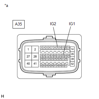
*a | Front view of wire harness connector
(to Skid Control ECU (Brake Booster with Master Cylinder Assembly)) | | |
(b) Make sure that there is no looseness at the locking part and the connecting part of the connector.
OK: The connector is securely connected. (c) Disconnect the A35 skid control ECU (brake booster with master cylinder assembly) connector.
(d) Check both the connector case and the terminals for deformation and corrosion.
OK: No deformation or corrosion. (e) Turn the power switch on (IG).
(f) Measure the voltage according to the value(s) in the table below. Standard Voltage: |
Tester Connection | Condition |
Specified Condition | |
A35-23 (IG1) - Body ground |
Power switch on (IG) |
11 to 14 V | |
A35-9 (IG2) - Body ground |
Power switch on (IG) |
11 to 14 V |
|
Result | Proceed to | |
11 to 14 V. | A | |
Below 11 V. | B |
| A |
| REPLACE BRAKE BOOSTER WITH MASTER CYLINDER ASSEMBLY |
| B |
| REPAIR OR REPLACE HARNESS OR CONNECTOR (IG1 AND/OR IG2 CIRCUIT) | |


