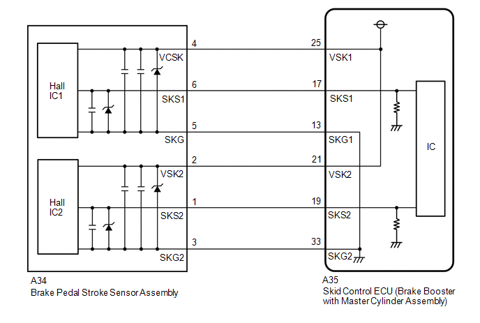
DESCRIPTION The brake pedal
stroke sensor assembly sends a signal about the pedal stroke to the
skid control ECU (brake booster with master cylinder assembly). |
DTC No. | Detection Item |
INF Code | DTC Detection Condition |
Trouble Area | MIL |
Note | | C1247 |
Stroke Sensor | 211
212 213 214 215 216 217 |
- INF Code: 211
- The sensor supply voltage (VCSK) is 4.7 V or less, or 5.3 V or more for 0.2 seconds or more.
- INF Code: 212
- The sensor output voltage 1 (SKS1) is less than 0.3 V, or 4.7 V or more for 0.2 seconds or more.
- INF Code: 213
- The sensor output voltage 2 (SKS2) is less than 0.3 V, or 4.7 V or more for 0.2 seconds or more.
- INF Code: 214
- The difference between the current value and previous value of the
sensor output voltage 1 (SKS1) is 8.5% or more for 0.2 seconds or more.
- INF Code: 215
- The difference between the current value and previous value of the
sensor output voltage 2 (SKS2) is 8.5% or more for 0.2 seconds or more.
- INF Code: 216
- INF Code: 217
|
- INF Code: 211
- Open or short in brake pedal stroke sensor assembly power supply circuit
- Improperly connected connector, deformation or corrosion of terminals
- Skid control ECU (brake booster with master cylinder assembly)
- INF Code: 212, 213, 214, 215, 216, 217
- Open or short in wire harness
- Improperly connected connector, deformation or corrosion of terminals
- Brake pedal stroke sensor assembly
| Comes on |
- INF Code 211: SAE Code C0562
- INF Code 212: SAE Code P057C and P057D
- INF Code 213: SAE Code P05DD and P05DE
- INF Code 214: SAE Code P057E
- INF Code 215: SAE Code P05DF
- INF Code 216: SAE Code P05E0
- INF Code 217: SAE Code C124B
- Electronically controlled brake system DTC
| | C1392 |
Zero Point Calibration of Stroke Sensor undone |
1124 | The brake pedal stroke sensor assembly zero point calibration is not performed.
(Normal brake pedal stroke sensor assembly zero point not memorized.) |
Normal brake pedal stroke sensor assembly zero point not memorized.
(Linear solenoid valve offset learning is not performed or Test Mode is not performed or not complete.) |
Only DTC C1392 (INF code 1124) is stored: Does not come on SAE Code C1392 is stored: Comes on |
- INF Code 1124: SAE Code C1392
- Electronically controlled brake system DTC
HINT: During Test Mode, related DTCs are cleared (except SAE code). | MONITOR DESCRIPTION C0562:
- The skid control ECU (brake booster with master cylinder assembly)
monitors the power supply voltage of the brake pedal stroke sensor
assembly. When the brake pedal stroke sensor assembly power supply
voltage is outside of the normal range, the skid control ECU (brake
booster with master cylinder assembly) judges that the power supply is
abnormal and illuminates the MIL and stores this DTC.
C124B:
- When the following conditions are met, the skid control ECU (brake
booster with master cylinder assembly) judges that the data from the
brake pedal stroke sensor assembly is invalid and illuminates the MIL
and stores this DTC.
- Brake pedal stroke sensor assembly related DTCs (C0562, P057D, P05DE, P057C, P05DD, P05E0, P057E and P05DF) are not stored.
- When related malfunction DTCs are not stored, the skid control ECU
(brake booster with master cylinder assembly) continuously detects a
brake pedal stroke sensor assembly malfunction.
SAE Code C1392:
- After any of the following situations, if the zero point of the brake
pedal stroke sensor 1 or brake pedal stroke sensor 2 has not been
learned and the vehicle is being driven at a certain speed or more, the
skid control ECU (brake booster with master cylinder assembly) judges
that the zero point of the brake pedal stroke sensor is uncalibrated and
illuminates the MIL and stores this DTC.
- The skid control ECU (brake booster with master cylinder assembly) has been replaced with a new one.
- After the brake actuator assembly, brake pedal stroke sensor assembly or
brake pedal is removed and installed or replaced, the zero point is
cleared.
P057C, P057D, P057E, P05DD, P05DE, P05DF and P05E0:
- The skid control ECU (brake booster with master cylinder assembly)
monitors the output value of the brake pedal stroke sensor assembly, and
if the following conditions are detected, the skid control ECU (brake
booster with master cylinder assembly) judges that the brake pedal
stroke sensor assembly has a malfunction and illuminates the MIL and
stores a DTC.
- The power supply voltage ratio of the brake pedal stroke sensor 1 and brake pedal stroke sensor 2 is outside the normal range.
HINT:
The power supply voltage ratio is the ratio of the voltage of SKS1 and VSK1 or SKS2 and VSK2.
- When the brake pedal is operated, the relationship between the value
output by the brake pedal stroke sensor 1 and brake pedal stroke sensor 2
is outside the normal range.
- The difference between the current power supply voltage ratio and the
previous power supply voltage ratio of the brake pedal stroke sensor 1
and brake pedal stroke sensor 2 exceeds a specific value (improbable
sudden change repeats).
HINT:
The power supply voltage ratio is the ratio of the voltage of SKS1 and VSK1 or SKS2 and VSK2.
C1392 (INF Code 1124):
- After any of the following situations, if the zero point of the brake
pedal stroke sensor 1 or brake pedal stroke sensor 2 has not been
learned, the skid control ECU (brake booster with master cylinder
assembly) judges that the zero point of the brake pedal stroke sensor is
uncalibrated and illuminates the ABS warning, brake warning / red
(malfunction), brake warning / yellow (minor malfunction) and slip
indicator lights, blinks* the brake hold operated indicator light and
stores this DTC.
- The skid control ECU (brake booster with master cylinder assembly) has been replaced with a new one.
- After the brake actuator assembly, brake pedal stroke sensor assembly or
brake pedal is removed and installed or replaced, the zero point is
cleared.
HINT:
- *: The brake hold switch (electric parking brake switch assembly) is turned on under the following vehicle conditions.
- Vehicle Conditions:
- The driver side door is closed.
- The driver side seat belt is fastened.
- As the detection conditions slightly differ from SAE code C1392, the
detection conditions for DTC C1392 (INF code 1124) is also provided.
MONITOR STRATEGY HINT: SAE code only. |
Related DTCs | C0562: Brake pedal stroke sensor assembly voltage circuit/open
C124B: Brake pedal stroke sensor assembly invalid data C1392: Brake pedal stroke sensor learning not complete
P057C: Brake pedal stroke sensor assembly open circuit P057D: Brake pedal stroke sensor assembly circuit high
P057E: Brake pedal stroke sensor assembly intermittent/erratic P05DD: Brake pedal stroke sensor assembly open circuit
P05DE: Brake pedal stroke sensor assembly circuit high P05DF: Brake pedal stroke sensor assembly intermittent/erratic
P05E0: Brake pedal stroke sensor assembly "1"/"2" correlation | |
Required Sensors/Components(Main) | Brake pedal stroke sensor assembly
Skid control ECU (brake booster with master cylinder assembly) | |
Required Sensors/Components(Related) | Skid control ECU (brake booster with master cylinder assembly)
Brake pedal stroke sensor assembly Speed sensor | |
Frequency of Operation | Continuous | |
Duration | -: C1392 0.2 seconds: C0562, C124B, P057C, P057D, P057E, P05DD, P05DE, P05DF and P05E0 | |
MIL Operation | Immediately | |
Sequence of Operation | None | TYPICAL ENABLING CONDITIONS
HINT: SAE code only. C0562 |
Monitor runs whenever the following DTCs are not stored |
None | | Brake system voltage 1 (VM1) |
Higher than 6.92 V | C124B |
Monitor runs whenever the following DTCs are not stored |
C0562 (Brake pedal stroke sensor assembly voltage circuit/open) P057C, P05DD (Brake pedal stroke sensor assembly open circuit)
P057D, P05DE (Brake pedal stroke sensor assembly circuit high) P057E, P05DF (Brake pedal stroke sensor assembly intermittent/erratic)
P05E0 (Brake pedal stroke sensor assembly "1"/"2" correlation) | |
All of the following conditions are met | - | |
Brake system voltage 1 (VM1) | Higher than 6.92 V | |
Serial communication with high side IC | Valid | |
Brake pedal stroke sensor assembly fail (C0562, P057C, P057D, P057E, P05DD, P05DE, P05DF, P05E0) |
Not detected | C1392 |
Monitor runs whenever the following DTCs are not stored |
None | | Vehicle speed | 40 km/h (25 mph) or more | P057C, P057D, P057E, P05DD, P05DE and P05DF |
Monitor runs whenever the following DTCs are not stored |
None | | Brake pedal stroke sensor assembly power supply |
4.74 V or more, and 5.23 V or less | P05E0 |
Monitor runs whenever the following DTCs are not stored |
C0562 (Brake pedal stroke sensor assembly voltage circuit/open) C124B (Brake pedal stroke sensor assembly invalid data)
P057C, P05DD (Brake pedal stroke sensor assembly open circuit) P057D, P05DE (Brake pedal stroke sensor assembly circuit high)
P057E, P05DF (Brake pedal stroke sensor assembly intermittent/erratic) | |
Both of the following conditions are met | - | |
Brake system voltage 1 (VM1) | Higher than 6.92 V | |
Brake pedal stroke sensor assembly fail (C0562, C124B, P057C, P057D, P057E, P05DD, P05DE, P05DF) |
Not detected | TYPICAL MALFUNCTION THRESHOLDS
HINT: SAE code only. C0562 |
Brake pedal stroke sensor assembly power supply | Less than 4.74 V, or higher than 5.23 V | C124B |
Brake pedal stroke sensor assembly state | Invalid | C1392 |
Either of the following conditions is met | - | |
Brake pedal stroke sensor 1 zero point calibration value |
Not stored | | Brake pedal stroke sensor 2 zero point calibration value |
Not stored | P057C and P05DD |
Power supply voltage ratio of SKS and VSK | Less than 0.06 |
HINT: The power supply voltage ratio is the ratio of the voltage of SKS1 and VSK1 or SKS2 and VSK2. P057D and P05DE |
Power supply voltage ratio of SKS and VSK | Higher than 0.94 |
HINT: The power supply voltage ratio is the ratio of the voltage of SKS1 and VSK1 or SKS2 and VSK2. P057E and P05DF |
Difference between the current power supply voltage ratio and the previous power supply voltage ratio of SKS and VSK |
Higher than 8.5% | HINT: The power supply voltage ratio is the ratio of the voltage of SKS1 and VSK1 or SKS2 and VSK2. P05E0 |
Brake pedal stroke sensor assembly correlation state | Invalid | COMPONENT OPERATING RANGE
HINT: SAE code only. C0562 |
Both of the following conditions are met |
- | | Brake system voltage 1 (VM1) |
Higher than 6.92 V | | Brake pedal stroke sensor assembly power supply |
4.74 V or more, and 5.23 V or less | C124B |
Both of the following conditions are met |
- | | Brake system voltage 1 (VM1) |
Higher than 6.92 V | | Brake pedal stroke sensor assembly state |
Valid | C1392 |
Both of the following conditions are met | - | |
Brake pedal stroke sensor 1 zero point calibration value |
Stored | | Brake pedal stroke sensor 2 zero point calibration value |
Stored | P057C, P05DD, P057D and P05DE |
Both of the following conditions are met |
- | | Brake pedal stroke sensor assembly power supply |
4.74 V or more, and 5.23 V or less | | Power supply voltage ratio of SKS and VSK |
0.06 or more, and 0.94 or less | HINT:
The power supply voltage ratio is the ratio of the voltage of SKS1 and VSK1 or SKS2 and VSK2. P057E and P05DF |
Both of the following conditions are met |
- | | Brake pedal stroke sensor assembly power supply |
4.74 V or more, and 5.23 V or less | | Difference between the current power supply voltage ratio and the previous power supply voltage ratio of SKS and VSK |
8.5% or less | HINT: The power supply voltage ratio is the ratio of the voltage of SKS1 and VSK1 or SKS2 and VSK2. P05E0 |
Both of the following conditions are met |
- | | Brake system voltage 1 (VM1) |
Higher than 6.92 V | | Brake pedal stroke sensor assembly on experience (low/mid/high) |
On | CONFIRMATION DRIVING PATTERN
- Connect the Techstream to the DLC3.
- Turn the power switch on (IG).
- Turn the Techstream on.
- Clear the DTCs (even if no DTCs are stored, perform the clear DTC procedure).
- Turn the power switch off.
- Turn the power switch on (READY).
- Turn the Techstream on.
- Fully depress the brake pedal.
- Drive the vehicle at a speed of 40 km/h (25 mph) or more for 1 minute.
HINT:
Only DTC C1392 is stored when the vehicle speed reaches 40 km/h (25 mph).
- Enter the following menus: Chassis / ABS/VSC/TRAC / Trouble Codes.
- Read the DTCs.
HINT:
- If a DTC is output, the system is malfunctioning.
- If a DTC is not output, perform the following procedure.
- If the DTCs are not output, perform a universal trip and check for permanent DTCs.
Click here 
HINT:
- If a permanent DTC is output, the system is malfunctioning.
- If no permanent DTCs are output, the system is normal.
WIRING DIAGRAM
 CAUTION / NOTICE / HINT
NOTICE: After
replacing the skid control ECU (brake booster with master cylinder
assembly) or brake pedal stroke sensor assembly, perform linear solenoid
valve offset learning, ABS holding solenoid valve learning, yaw rate
and acceleration sensor zero point calibration and system information
memorization after performing "Reset Memory". Click here
HINT: Check the condition of each related circuit connector before troubleshooting.
Click here PROCEDURE
(a)
Check that the brake pedal and the brake pedal stroke sensor assembly
are properly installed and that the pedal can be depressed normally. (b) Check and adjust the brake pedal height.
Click here (c) Adjust the brake pedal stroke sensor assembly.
Click here
|
NEXT |
 | |
(a) Clear the DTCs. Click here
Chassis > ABS/VSC/TRAC > Clear DTCs
(b) Turn the power switch off. (c) Turn the power switch on (IG).
(d) Check if the same DTC is output. Click here
Chassis > ABS/VSC/TRAC > Trouble Codes
| Result |
Proceed to | | DTC C1247 is output. |
A | | DTC C1392 is output. |
B |
| B |
 | GO TO STEP 7 |
|
A | |
| |
| 3. |
CHECK FREEZE FRAME DATA | (a) Check the INF code from the Freeze Frame Data stored when DTC (C1247) was stored.
Click here Chassis > ABS/VSC/TRAC > Trouble Codes
|
Result | Proceed to | |
INF code 211 is output. |
A | | INF code 212, 213, 214, 215, 216 or 217 is output. |
B |
| B |
| GO TO STEP 6 |
|
A | |
| |
| 4. |
CHECK HARNESS AND CONNECTOR (BRAKE BOOSTER WITH MASTER CYLINDER ASSEMBLY - BRAKE PEDAL STROKE SENSOR ASSEMBLY) |
(a) Turn the power switch off. (b) Make sure that there is no looseness at the locking part and the connecting part of the connectors.
OK: The connector is securely connected. (c) Disconnect the A35 skid control ECU (brake booster with master cylinder assembly) connector.
(d) Disconnect the A34 brake pedal stroke sensor assembly connector. (e) Check both the connector case and the terminals for deformation and corrosion.
OK: No deformation or corrosion. (f) Measure the resistance according to the value(s) in the table below.
Standard Resistance: |
Tester Connection | Condition |
Specified Condition | |
A35-13 (SKG1) - A34-5 (SKG) |
Always | Below 1 Ω | |
A35-13 (SKG1) or A34-5 (SKG) - Body ground |
Always | 10 kΩ or higher | |
A35-21 (VSK2) - A34-2 (VSK2) |
Always | Below 1 Ω | |
A35-21 (VSK2) or A34-2 (VSK2) - Body ground |
Always | 10 kΩ or higher | |
A35-25 (VSK1) - A34-4 (VCSK) |
Always | Below 1 Ω | |
A35-25 (VSK1) or A34-4 (VCSK) - Body ground |
Always | 10 kΩ or higher | |
A35-33 (SKG2) - A34-3 (SKG2) |
Always | Below 1 Ω | |
A35-33 (SKG2) or A34-3 (SKG2) - Body ground |
Always | 10 kΩ or higher |
| NG |
| REPAIR OR REPLACE HARNESS OR CONNECTOR |
|
OK | |
| |
| 5. |
INSPECT BRAKE BOOSTER WITH MASTER CYLINDER ASSEMBLY (SENSOR OUTPUT) |
| (a) Reconnect the A35 skid control ECU (brake booster with master cylinder assembly) connector. |
 |
|
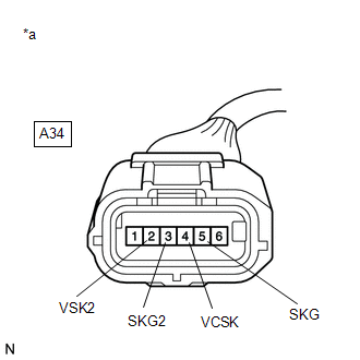
*a | Front view of wire harness connector
(to Brake Pedal Stroke Sensor Assembly) | | |
(b) Turn the power switch on (IG). (c) Measure the voltage according to the value(s) in the table below.
Standard Voltage: |
Tester Connection | Condition |
Specified Condition | |
A34-4 (VCSK) - A34-5 (SKG) |
Power switch on (IG) |
4.84 to 5.16 V | |
A34-2 (VSK2) - A34-3 (SKG2) |
Power switch on (IG) |
4.84 to 5.16 V |
| OK |
| REPLACE BRAKE PEDAL STROKE SENSOR ASSEMBLY |
| NG |
| REPLACE BRAKE BOOSTER WITH MASTER CYLINDER ASSEMBLY |
| 6. |
CHECK HARNESS AND CONNECTOR (BRAKE BOOSTER WITH MASTER CYLINDER ASSEMBLY - BRAKE PEDAL STROKE SENSOR ASSEMBLY) |
(a) Turn the power switch off. (b) Make sure that there is no looseness at the locking part and the connecting part of the connectors.
OK: The connector is securely connected. (c) Disconnect the A35 skid control ECU (brake booster with master cylinder assembly) connector.
(d) Disconnect the A34 brake pedal stroke sensor assembly connector. (e) Check both the connector case and the terminals for deformation and corrosion.
OK: No deformation or corrosion. (f) Measure the resistance according to the value(s) in the table below.
Standard Resistance: |
Tester Connection | Condition |
Specified Condition | |
A35-17 (SKS1) - A34-6 (SKS1) |
Always | Below 1 Ω | |
A35-17 (SKS1) or A34-6 (SKS1) - Body ground |
Always | 10 kΩ or higher | |
A35-19 (SKS2) - A34-1 (SKS2) |
Always | Below 1 Ω | |
A35-19 (SKS2) or A34-1 (SKS2) - Body ground |
Always | 10 kΩ or higher |
| OK |
| REPLACE BRAKE PEDAL STROKE SENSOR ASSEMBLY |
| NG |
| REPAIR OR REPLACE HARNESS OR CONNECTOR |
| 7. |
PERFORM BRAKE PEDAL STROKE SENSOR ASSEMBLY ZERO POINT CALIBRATION |
(a) Perform brake pedal stroke sensor assembly zero point calibration.
Click here NOTICE: Make
sure to perform linear solenoid valve offset learning, ABS holding
solenoid valve learning, brake pedal stroke sensor assembly zero point
calibration and system information memorization after performing "Reset
Memory" as the data stored during linear solenoid valve offset learning,
ABS holding solenoid valve learning, brake pedal stroke sensor assembly
zero point calibration and system information memorization is cleared. Chassis > ABS/VSC/TRAC > Utility
|
Tester Display | | Reset Memory | Chassis > ABS/VSC/TRAC > Utility
|
Tester Display | | ECB Utility |
|
NEXT | |
| |
(a) Clear the DTCs.
Click here Chassis > ABS/VSC/TRAC > Clear DTCs
(b) Turn the power switch off. (c) Turn the power switch on (IG).
(d) Check if the same DTC is output. Click here
Chassis > ABS/VSC/TRAC > Trouble Codes
| Result |
Proceed to | | DTC C1392 is output. |
A | | DTCs are not output. |
B | | DTCs other than C1392 are output. |
C |
| B |
| END |
| C |
| REPAIR CIRCUITS INDICATED BY OUTPUT DTCS |
|
A | |
| |
| 9. |
INSPECT BRAKE BOOSTER WITH MASTER CYLINDER ASSEMBLY (SENSOR OUTPUT) |
| (a) Turn the power switch off. | |
|
|
*a | Front view of wire harness connector
(to Brake Pedal Stroke Sensor Assembly) | | |
(b) Make sure that there is no looseness at the locking part and the connecting part of the connectors.
OK: The connector is securely connected. (c) Disconnect the A34 brake pedal stroke sensor assembly connector.
(d) Check both the connector case and the terminals for deformation and corrosion.
OK: No deformation or corrosion. (e) Turn the power switch on (IG).
(f) Measure the voltage according to the value(s) in the table below. Standard Voltage: |
Tester Connection | Condition |
Specified Condition | |
A34-4 (VCSK) - A34-5 (SKG) |
Power switch on (IG) |
4.84 to 5.16 V | |
A34-2 (VSK2) - A34-3 (SKG2) |
Power switch on (IG) |
4.84 to 5.16 V |
| OK |
| REPLACE BRAKE PEDAL STROKE SENSOR ASSEMBLY |
| NG |
| REPLACE BRAKE BOOSTER WITH MASTER CYLINDER ASSEMBLY | |


