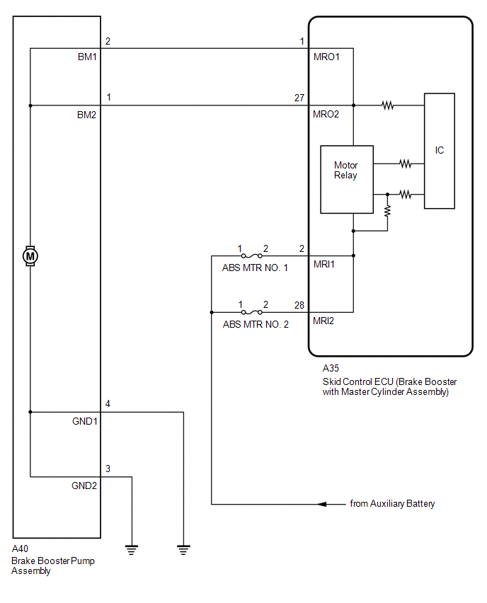
DESCRIPTION The skid
control ECU (brake booster with master cylinder assembly) detects
decreases in the accumulator pressure according to the data from the
accumulator pressure sensor, and then starts and stops the pump motor by
operating the motor relay. |
DTC No. | Detection Item |
INF Code | DTC Detection Condition |
Trouble Area | MIL |
Note | | C1252 |
Brake Booster Pump Motor on Time Abnormally Long |
311 | The pump motor is operating continuously for 178 seconds or more. (When the relay is malfunctioning for 98 seconds or more.) |
- Short in pump motor circuit or pump motor monitor circuit
- Motor relay stuck
- Accumulator pressure sensor malfunction
- Skid control ECU (brake booster with master cylinder assembly)
| Comes on |
- INF Code 311: SAE Code C0594
- Electronically controlled brake system DTC
| | C1253 |
Pump Motor Relay | 321
322 327 328 |
- INF Code: 321, 327, 328
- An open is detected in the motor relay drive circuit for 0.2 seconds or more.
- INF Code: 322
- A short is detected in the motor relay drive circuit for 2 seconds or more.
|
- INF Code: 321, 327, 328
- Open in pump motor circuit or pump motor monitor circuit
- Skid control ECU (brake booster with master cylinder assembly)
- INF Code: 322
- Short in pump motor circuit or pump motor monitor circuit
- Skid control ECU (brake booster with master cylinder assembly)
| Comes on (When only SAE code C121D or SAE code C121E is stored) |
- INF Code 321: SAE Code C121D
- INF Code 322: SAE Code C121E
- Electronically controlled brake system DTC
| MONITOR DESCRIPTION
The skid control ECU (brake booster with master cylinder assembly) monitors the voltage of the pump motor.
When
the pump motor relay is instructed to be on and the voltage of the pump
motor is within the range of an open circuit malfunction (voltage value
is practically equal to that when off), or when the pump motor is
instructed to be off and the voltage of the pump motor is within the
range of a short circuit malfunction (voltage value is practically equal
to that when on), an open circuit or short circuit is judged
respectively and the MIL is illuminated and stores a DTC. Furthermore,
when the voltage of the pump motor is practically equal to that when on
for a long period of time, the skid control ECU (brake booster with
master cylinder assembly) judges that the pump motor is operating for an
abnormally long time and illuminates the MIL and stores a DTC. MONITOR STRATEGY |
Related DTCs | C0594: Pump motor performance C121D: Pump motor open circuit
C121E: Pump motor circuit high | |
Required Sensors/Components(Main) | Brake booster pump assembly | |
Required Sensors/Components(Related) | Skid control ECU (brake booster with master cylinder assembly)
Brake booster pump assembly Brake actuator (brake booster with master cylinder assembly) | |
Frequency of Operation | Continuous | |
Duration | 0.2 seconds: C121D 2 seconds: C121E
98 seconds: C0594 (Case 1) 178 seconds: C0594 (Case 2) | |
MIL Operation | Immediately | |
Sequence of Operation | None | TYPICAL ENABLING CONDITIONS C0594 (Case 1) |
Monitor runs whenever the following DTCs are not stored |
None | | Both of the following conditions are met |
A and B | | A. Serial communication with high side IC |
Valid | | B. One of the following conditions is met |
a, b or c | | a. Pump motor circuit fail (C121D) |
Detected | | b. Pump motor circuit fail (C121E) |
Detected | | c. Both of the following conditions are met |
- | | Accumulator pressure sensor |
Valid | | Accumulator pressure |
Higher than 19.88 MPa (202.7 kgf/cm2, 2884 psi) | C0594 (Case 2) |
Monitor runs whenever the following DTCs are not stored |
None | | Serial communication with high side IC |
Valid | C121D |
Monitor runs whenever the following DTCs are not stored |
None | | Both of the following conditions are met |
A and B | | A. Serial communication with high side IC |
Valid | | B. Either of the following conditions is met |
a or b | | a. Command to pump motor relay |
On | | b. Both of the following conditions are met |
- | | Command to pump motor relay from hardware |
On | | Serial communication with low side IC |
Valid | C121E |
Monitor runs whenever the following DTCs are not stored |
None | | All of the following conditions are met |
- | | Serial communication with high side IC |
Valid | | Serial communication with low side IC |
Valid | | Command to pump motor relay |
Off | | Command to pump motor relay from hardware |
Off | TYPICAL MALFUNCTION THRESHOLDS C0594 (Case 1), C0594 (Case 2) and C121E |
Pump motor voltage | Higher than 6 V | C121D |
Pump motor voltage | Less than 6 V | COMPONENT OPERATING RANGE C0594 |
Both of the following conditions are met |
- | | Prohibit pump motor operating from microcomputer |
Off | | Pump motor voltage |
Less than 6 V | C121D |
All of the following conditions are met | A, B and C | |
A. Serial communication with high side IC | Valid | |
B. Either of the following conditions is met | a or b | |
a. Command to pump motor relay | On | |
b. Both of the following conditions are met | - | |
Command to pump motor relay from hardware | On | |
Serial communication with low side IC | Valid | |
C. Pump motor voltage | Higher than 6 V | C121E |
Both of the following conditions are met |
- | | Serial communication with high side IC |
Valid | | Pump motor voltage |
Less than 6 V | CONFIRMATION DRIVING PATTERN
- Connect the Techstream to the DLC3.
- Turn the power switch on (IG).
- Turn the Techstream on.
- Clear the DTCs (even if no DTCs are stored, perform the clear DTC procedure).
- Turn the power switch off.
- Turn the power switch on (IG).
- Turn the Techstream on.
- Depress the brake pedal several times until the pump motor operates.
- Wait 3 minutes.
- Enter the following menus: Chassis / ABS/VSC/TRAC / Trouble Codes.
- Read the DTCs.
HINT:
- If a DTC is output, the system is malfunctioning.
- If a DTC is not output, perform the following procedure.
- If the DTCs are not output, perform a universal trip and check for permanent DTCs.
Click here 
HINT:
- If a permanent DTC is output, the system is malfunctioning.
- If no permanent DTCs are output, the system is normal.
WIRING DIAGRAM
 CAUTION / NOTICE / HINT
NOTICE:
- After replacing the skid control ECU (brake booster with master cylinder
assembly), perform linear solenoid valve offset learning, ABS holding
solenoid valve learning, yaw rate and acceleration sensor zero point
calibration and system information memorization after performing "Reset
Memory".
Click here
- Inspect the fuses for circuits related to this system before performing the following procedure.
PROCEDURE (a) Check the DTCs that are output.
Click here Chassis > ABS/VSC/TRAC > Trouble Codes
| Result |
Proceed to | | DTCs C1252 and/or C1253 are output. |
A | | DTCs C1241 and/or C1242 are output with DTCs C1252 and/or C1253. |
B |
| B |
 | REPAIR CIRCUITS INDICATED BY OUTPUT DTCS |
|
A |
 | |
| 2. |
READ VALUE USING TECHSTREAM (MOTOR RELAY 1 AND MOTOR RELAY 2) |
(a) Select the Data List on the Techstream. Click here
Chassis > ABS/VSC/TRAC > Data List
|
Tester Display | Measurement Item |
Range | Normal Condition |
Diagnostic Note | |
ECB Motor Relay | Motor relay 1 operation request |
ON or OFF | ON: Relay on
OFF: Relay off | ECB: Electronically Controlled Brake System | |
ECB Motor Relay2 | Motor relay 2 operation request |
ON or OFF | ON: Relay on
OFF: Relay off | ECB: Electronically Controlled Brake System | Chassis > ABS/VSC/TRAC > Data List
|
Tester Display | | ECB Motor Relay | |
ECB Motor Relay2 | (b) Depress the brake pedal several times and check the operation status of the motor relay 1 and motor relay 2.
HINT: Depressing the brake pedal several times drops the accumulator pressure and operates the pump motor.
| Result |
Proceed to | | The motor relay 1 and motor relay 2 in the Data List turns on or off by depressing the brake pedal several times. |
A | | The
status of motor relay 1 and motor relay 2 in the Data List does not
change even after depressing the brake pedal several times. |
B |
| B |
| GO TO STEP 8 |
|
A | |
| |
| 3. |
INSPECT BRAKE BOOSTER PUMP ASSEMBLY |
| (a) Turn the power switch off. |
 |
|
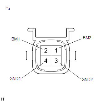
*a | Component without harness connected
(Brake Booster Pump Assembly) | | |
(b) Make sure that there is no looseness at the locking part and the connecting part of the connector.
OK: The connector is securely connected. (c) Disconnect the A40 brake booster pump assembly connector.
(d) Check both the connector case and the terminals for deformation and corrosion.
OK: No deformation or corrosion. (e) Measure the resistance according to the value(s) in the table below.
Standard Resistance: |
Tester Connection | Condition |
Specified Condition | |
2 (BM1) - 4 (GND1) | Always |
10 Ω or less | |
1 (BM2) - 3 (GND2) | Always |
10 Ω or less | |
2 (BM1) - 1 (BM2) | Always |
Below 1 Ω | |
4 (GND1) - 3 (GND2) | Always |
Below 1 Ω |
| NG |
| REPLACE BRAKE BOOSTER PUMP ASSEMBLY |
|
OK | |
| |
| 4. |
CHECK HARNESS AND CONNECTOR (GND TERMINAL) |
| (a) Measure the resistance according to the value(s) in the table below.
Standard Resistance: |
Tester Connection | Condition |
Specified Condition | |
A40-4 (GND1) - Body ground |
Always | Below 1 Ω | |
A40-3 (GND2) - Body ground |
Always | Below 1 Ω | |
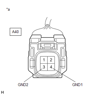 |
|
*a | Front view of wire harness connector
(to Brake Booster Pump Assembly) | | |
| NG |
| REPAIR OR REPLACE HARNESS OR CONNECTOR (GND CIRCUIT) |
|
OK | |
| |
| 5. |
READ VALUE USING TECHSTREAM (ACCUMULATOR PRESSURE) |
(a) Reconnect the A40 brake booster pump assembly connector. (b) Disconnect the A34 brake pedal stroke sensor assembly connector.
(c) Select the Data List on the Techstream. Click here
Chassis > ABS/VSC/TRAC > Data List
|
Tester Display | Measurement Item |
Range | Normal Condition |
Diagnostic Note | |
MT Voltage Value | MT voltage value |
Min.: 0.00 V, Max.: 20.00 V |
Pump motor off: 0.00 V Pump motor on: 12.00 V |
- | | Accumulator Pressure |
Accumulator pressure output value |
Min.: 0.00 MPa, Max.: 24.48 MPa |
15.00 to 21.00 MPa (Pressure stable and pump motor stopped) |
When
brake fluid is stored in the accumulator: Accumulator pressure changes
in accordance with volume of fluid stored in the accumulator | Chassis > ABS/VSC/TRAC > Data List
|
Tester Display | | MT Voltage Value | |
Accumulator Pressure | (d) Depress the brake pedal several times to operate the pump motor, then wait until it stops.
(e)
After the pump motor stops, wait for 30 seconds, then check the drop in
the accumulator pressure sensor output value and the state of the pump
motor.
HINT:
- This inspection checks whether an accumulator pressure sensor
malfunction, internal brake actuator (brake booster with master cylinder
assembly) leak or prolonged operation due to detection of low pressure
caused by accumulator deterioration, caused the DTC to be stored.
- If the brake fluid level in the brake master cylinder reservoir assembly
(brake booster with master cylinder assembly) drops, an external brake
fluid leak is suspected.
| Result |
Proceed to | | The
drop in the accumulator pressure sensor output value is less than 2.50
MPa 30 seconds after the pump motor stops, and the pump motor does not
operate within 30 seconds after the pump motor stops. |
A | | The
drop in the accumulator pressure sensor output value is 2.50 MPa or
more 30 seconds after the pump motor stops, or the pump motor operates
within 30 seconds after the pump motor stops. |
B |
| B |
| GO TO STEP 7 |
|
A | |
| |
(a) Turn the power switch off.
(b) Reconnect the A34 brake pedal stroke sensor assembly connector. (c) Clear the DTCs.
Click here Chassis > ABS/VSC/TRAC > Clear DTCs
(d) Turn the power switch off. (e) Turn the power switch on (IG).
(f) Check if the same DTC is output. Click here
Chassis > ABS/VSC/TRAC > Trouble Codes
| Result |
Proceed to | | DTCs C1252 and C1253 are not output. |
A | | DTCs C1252 and/or C1253 are output. |
B |
| A |
| USE SIMULATION METHOD TO CHECK |
| B |
| REPLACE BRAKE BOOSTER WITH MASTER CYLINDER ASSEMBLY |
| 7. |
READ VALUE USING TECHSTREAM (SERVO PRESSURE) |
(a) Turn the power switch off. (b) Reconnect the A34 brake pedal stroke sensor assembly connector.
(c) Select the Active Test on the Techstream. Click here
Chassis > ABS/VSC/TRAC > Active Test
|
Tester Display | Measurement Item |
Control Range | Diagnostic Note | |
ECB Solenoid (SLR) | Linear solenoid reduction valve (SLR) |
Solenoid ON/OFF | ECB: Electronically Controlled Brake System | Chassis > ABS/VSC/TRAC > Data List
|
Tester Display | Measurement Item |
Range | Normal Condition |
Diagnostic Note | |
Servo Pressure | Pressure value of servo |
Min.: 0.00 MPa, Max.: 24.48 MPa |
Brake pedal released: 0.00 to 2.10 MPa |
Brake pedal is being depressed: Changes in proportion to the depression force of the brake pedal | Chassis > ABS/VSC/TRAC > Active Test
|
Active Test Display | |
ECB Solenoid (SLR) |
|
Data List Display | |
Servo Pressure | (d)
Perform the Active Test and operate the linear solenoid (SLR) in the
brake actuator (brake booster with master cylinder assembly). (e) Check that the servo pressure output value does not increase when performing the Active Test.
OK: The servo pressure output value does not increase when performing the Active Test.
HINT: If
the servo pressure output value increases, an internal brake fluid leak
in the brake actuator (brake booster with master cylinder assembly) is
suspected. |
Result | Proceed to | |
The servo pressure output value increases. |
A | | The servo pressure output value does not increase. |
B |
| A |
| REPLACE BRAKE BOOSTER WITH MASTER CYLINDER ASSEMBLY |
| B |
| REPLACE BRAKE BOOSTER PUMP ASSEMBLY |
| 8. |
CHECK HARNESS AND CONNECTOR (MRI TERMINAL) |
| (a) Turn the power switch off. |
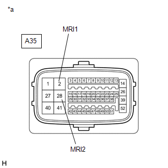 |
|
*a | Front view of wire harness connector
(to Skid Control ECU (Brake Booster with Master Cylinder Assembly)) | | |
(b) Make sure that there is no looseness at the locking part and the connecting part of the connector.
OK: The connector is securely connected. (c) Disconnect the A35 skid control ECU (brake booster with master cylinder assembly) connector.
(d) Check both the connector case and the terminals for deformation and corrosion.
OK: No deformation or corrosion. (e) Measure the voltage according to the value(s) in the table below.
Standard Voltage: |
Tester Connection | Condition |
Specified Condition | |
A35-2 (MRI1) - Body ground |
Always | 11 to 14 V | |
A35-28 (MRI2) - Body ground |
Always | 11 to 14 V |
| NG |
| REPAIR OR REPLACE HARNESS OR CONNECTOR (MRI CIRCUIT) |
|
OK | |
| |
| 9. |
CHECK HARNESS AND CONNECTOR (BRAKE BOOSTER WITH MASTER CYLINDER ASSEMBLY - BRAKE BOOSTER PUMP ASSEMBLY) |
(a) Make sure that there is no looseness at the locking part and the connecting part of the connector.
OK: The connector is securely connected. (b) Disconnect the A40 brake booster pump assembly connector.
(c) Check both the connector case and the terminals for deformation and corrosion.
OK: No deformation or corrosion. (d) Measure the resistance according to the value(s) in the table below.
Standard Resistance: |
Tester Connection | Condition |
Specified Condition | |
A35-1 (MRO1) - A40-2 (BM1) |
Always | Below 1 Ω | |
A35-1 (MRO1) or A40-2 (BM1) - Body ground |
Always | 10 kΩ or higher | |
A35-27 (MRO2) - A40-1 (BM2) |
Always | Below 1 Ω | |
A35-27 (MRO2) or A40-1 (BM2) - Body ground |
Always | 10 kΩ or higher |
| OK |
| REPLACE BRAKE BOOSTER WITH MASTER CYLINDER ASSEMBLY |
| NG |
| REPAIR OR REPLACE HARNESS OR CONNECTOR | | 

