DESCRIPTION The accumulator
pressure sensor is built into the brake actuator (brake booster with
master cylinder assembly) and detects the accumulator pressure. The
skid control ECU (brake booster with master cylinder assembly) turns on
the brake warning light / red (malfunction) and brake warning light /
yellow (minor malfunction), and sounds the meter buzzer if it senses a
decrease in the accumulator pressure. DTC C1256 may be stored if the accumulator pressure drops due to frequent braking (this is not a malfunction). |
DTC No. | Detection Item |
INF Code | DTC Detection Condition |
Trouble Area | MIL |
Note | | C1256 |
Accumulator Low Pressure |
341 1125 | Significant drop in accumulator pressure continues.
(DTCs will be stored and the buzzer will operate when either condition is met.) |
- Accumulator pressure dropped due to frequent brake pedal operation (not a malfunction)
- Pump motor malfunction
- Accumulator deterioration
- Accumulator pressure sensor (brake booster with master cylinder assembly)
- Supply voltage reduced
| Comes on (When only SAE code C1256 is stored) |
- INF Code 341: SAE Code C1256
- Electronically controlled brake system DTC
| MONITOR DESCRIPTION
The
skid control ECU (brake booster with master cylinder assembly) monitors
the value of the accumulator pressure using the accumulator pressure
sensor. If any of the following conditions are
met for a certain amount of time, the skid control ECU (brake booster
with master cylinder assembly) judges that the accumulator pressure is
low and illuminates the MIL and stores this DTC.
- The accumulator pressure does not increase when the pump motor is operated.
- The accumulator pressure is not a specific value or more after starting
the skid control ECU (brake booster with master cylinder assembly).
- The accumulator pressure is less than a specific value.
MONITOR STRATEGY |
Related DTCs | C1256: Accumulator pressure too low | |
Required Sensors/Components(Main) | Brake booster pump assembly
Brake actuator (brake booster with master cylinder assembly) | |
Required Sensors/Components(Related) | Skid control ECU (brake booster with master cylinder assembly)
Brake actuator (brake booster with master cylinder assembly) Stop light switch assembly
Brake booster pump assembly Brake pedal stroke sensor assembly | |
Frequency of Operation | Continuous | |
Duration | 1.7 to 9 seconds (Time depends on battery voltage): C1256 (Case 1)
3 seconds: C1256 (Case 2) 33 to 99 seconds (Time depends on battery voltage): C1256 (Case 3) | |
MIL Operation | Immediately | |
Sequence of Operation | None | TYPICAL ENABLING CONDITIONS All |
Monitor runs whenever the following DTCs are not stored |
C121E (Pump motor circuit high) C14D0 (Accumulator pressure sensor voltage circuit check)
C14D1 (Accumulator pressure sensor lost communication) C14D2 (Accumulator pressure sensor internal malfunction)
C14D3 (Accumulator pressure sensor intermittent/erratic) C14D4 (Case 1) (Accumulator pressure sensor invalid data)
C14D4 (Case 2) (Accumulator pressure sensor intermittent) | Case 1 |
All of the following conditions are met |
- | | Accumulator pressure sensor fail |
Not detected | | Accumulator pressure |
Less than 17.1 MPa (174.4 kgf/cm2, 2480 psi) | |
Brake | Off | | Brake system voltage 1 (VM1) |
Higher than 6.92 V | Case 2 |
All of the following conditions are met |
- | | Accumulator pressure sensor fail |
Not detected | | Accumulator pressure |
Less than 17.1 MPa (174.4 kgf/cm2, 2480 psi) | |
Pump motor control circuit high | Not detected | |
Brake | Off | |
Brake system voltage 1 (VM1) | Higher than 6.92 V | Case 3 |
Both of the following conditions are met |
- | | Accumulator pressure sensor fail |
Not detected | | Accumulator pressure |
Less than 17.1 MPa (174.4 kgf/cm2, 2480 psi) | TYPICAL MALFUNCTION THRESHOLDS Case 1 |
Accumulator pressure increase when pump motor is operating |
Less than 0.25 MPa (2.5 kgf/cm2, 36 psi) | Case 2 |
Accumulator pressure after skid control ECU (brake booster with master cylinder assembly) power on |
Less than 6 MPa (61.2 kgf/cm2, 870 psi) | Case 3 |
Accumulator pressure | Less than 14 MPa (142.8 kgf/cm2, 2031 psi) | COMPONENT OPERATING RANGE All |
Both of the following conditions are met |
- | | Accumulator pressure sensor fail |
Not detected | | Accumulator pressure |
17.1 MPa (174.4 kgf/cm2, 2480 psi) or more | CONFIRMATION DRIVING PATTERN
- Connect the Techstream to the DLC3.
- Turn the power switch on (IG).
- Turn the Techstream on.
- Clear the DTCs (even if no DTCs are stored, perform the clear DTC procedure).
- Turn the power switch off.
- Turn the power switch on (IG).
- Turn the Techstream on.
- Repeat the following step 10 times.
- Fully depress the brake pedal for 2 seconds, release it and wait 1 second.
- Wait 100 seconds.
- Enter the following menus: Chassis / ABS/VSC/TRAC / Trouble Codes.
- Read the DTCs.
HINT:
- If a DTC is output, the system is malfunctioning.
- If a DTC is not output, perform the following procedure.
- If the DTCs are not output, perform a universal trip and check for permanent DTCs.
Click here 
HINT:
- If a permanent DTC is output, the system is malfunctioning.
- If no permanent DTCs are output, the system is normal.
WIRING DIAGRAM Refer to DTCs C1252 and C1253.
Click here CAUTION / NOTICE / HINT
NOTICE:
- After replacing the skid control ECU (brake booster with master cylinder
assembly), perform linear solenoid valve offset learning, ABS holding
solenoid valve learning, yaw rate and acceleration sensor zero point
calibration and system information memorization after performing "Reset
Memory".
Click here
- Inspect the fuses for circuits related to this system before performing the following procedure.
PROCEDURE (a) Clear the DTCs.
Click here Chassis > ABS/VSC/TRAC > Clear DTCs
(b) Turn the power switch off. (c) Turn the power switch on (IG).
(d) Check if the same DTC is output. Click here
Chassis > ABS/VSC/TRAC > Trouble Codes
| Result |
Proceed to | | DTC C1256 is output. |
A | | DTCs C1202, C1241, C1252, C1253 and/or C1391 are output. |
B |
| B |
 | REPAIR CIRCUITS INDICATED BY OUTPUT DTCS |
|
A |
 | |
| 2. |
INSPECT BRAKE BOOSTER PUMP ASSEMBLY |
| (a) Turn the power switch off. |
 |
|
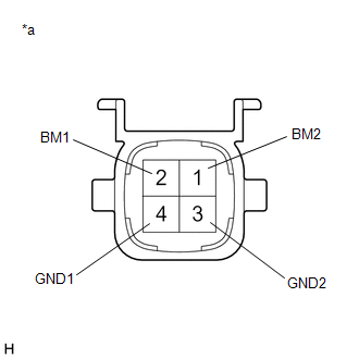
*a | Component without harness connected
(Brake Booster Pump Assembly) | | |
(b) Make sure that there is no looseness at the locking part and the connecting part of the connector.
OK: The connector is securely connected. (c) Disconnect the A40 brake booster pump assembly connector.
(d) Check both the connector case and the terminals for deformation and corrosion.
OK: No deformation or corrosion. (e) Measure the resistance according to the value(s) in the table below.
Standard Resistance: |
Tester Connection | Condition |
Specified Condition | |
2 (BM1) - 4 (GND1) | Always |
10 Ω or less | |
1 (BM2) - 3 (GND2) | Always |
10 Ω or less | |
2 (BM1) - 1 (BM2) | Always |
Below 1 Ω | |
4 (GND1) - 3 (GND2) | Always |
Below 1 Ω |
| NG |
| REPLACE BRAKE BOOSTER PUMP ASSEMBLY |
|
OK | |
| |
| 3. |
READ VALUE USING TECHSTREAM (ACCUMULATOR PRESSURE) |
(a) Reconnect the A40 brake booster pump assembly connector. (b) Disconnect the A34 brake pedal stroke sensor assembly connector.
(c) Select the Data List on the Techstream. Click here
Chassis > ABS/VSC/TRAC > Data List
|
Tester Display | Measurement Item |
Range | Normal Condition |
Diagnostic Note | |
MT Voltage Value | MT voltage value |
Min.: 0.00 V, Max.: 20.00 V |
Pump motor off: 0.00 V Pump motor on: 12.00 V |
- | | Accumulator Pressure |
Accumulator pressure output value |
Min.: 0.00 MPa, Max.: 24.48 MPa |
15.00 to 21.00 MPa (Pressure stable and pump motor stopped) |
When
brake fluid is stored in the accumulator: Accumulator pressure changes
in accordance with volume of fluid stored in the accumulator | Chassis > ABS/VSC/TRAC > Data List
|
Tester Display | | MT Voltage Value | |
Accumulator Pressure | (d) Depress the brake pedal several times to operate the pump motor, then wait until it stops.
(e)
After the pump motor stops, wait for 30 seconds, then check the drop in
the accumulator pressure sensor output value and the state of the pump
motor. | Result |
Proceed to | | The
drop in the accumulator pressure sensor output value is less than 2.50
MPa 30 seconds after the pump motor stops, and the pump motor does not
operate within 30 seconds after the pump motor stops. |
A | | The
drop in the accumulator pressure sensor output value is 2.50 MPa or
more 30 seconds after the pump motor stops, or the pump motor operates
within 30 seconds after the pump motor stops. |
B |
| A |
| USE SIMULATION METHOD TO CHECK |
|
B | |
| |
| 4. |
READ VALUE USING TECHSTREAM (SERVO PRESSURE) |
(a) Turn the power switch off. (b) Reconnect the A34 brake pedal stroke sensor assembly connector.
(c) Select the Active Test on the Techstream. Click here
Chassis > ABS/VSC/TRAC > Active Test
|
Tester Display | Measurement Item |
Control Range | Diagnostic Note | |
ECB Solenoid (SLR) | Linear solenoid reduction valve (SLR) |
Solenoid ON/OFF | ECB: Electronically Controlled Brake System | Chassis > ABS/VSC/TRAC > Data List
|
Tester Display | Measurement Item |
Range | Normal Condition |
Diagnostic Note | |
Servo Pressure | Pressure value of servo |
Min.: 0.00 MPa, Max.: 24.48 MPa |
Brake pedal released: 0.00 to 2.10 MPa |
Brake pedal is being depressed: Changes in proportion to the depression force of the brake pedal | Chassis > ABS/VSC/TRAC > Active Test
|
Active Test Display | |
ECB Solenoid (SLR) |
|
Data List Display | |
Servo Pressure | (d)
Perform the Active Test and operate the linear solenoid (SLR) in the
brake actuator (brake booster with master cylinder assembly). (e) Check that the servo pressure output value does not increase when performing the Active Test.
OK: The servo pressure output value does not increase when performing the Active Test.
HINT: If
the servo pressure output value increases, an internal brake fluid leak
in the brake actuator (brake booster with master cylinder assembly) is
suspected. |
Result | Proceed to | |
The servo pressure output value increases. |
A | | The servo pressure output value does not increase. |
B |
| A |
| REPLACE BRAKE BOOSTER WITH MASTER CYLINDER ASSEMBLY |
| B |
| REPLACE BRAKE BOOSTER WITH MASTER CYLINDER ASSEMBLY AND BRAKE BOOSTER PUMP ASSEMBLY | | 

