DESCRIPTION The main relay supplies power to the switching solenoid and the linear solenoid.
The
main relay remains on for approximately 2 minutes after the power
switch is turned off and the input of brake pedal operation signals
stops, and supplies power to the system to keep it ready to operate. |
DTC No. | Detection Item |
INF Code | DTC Detection Condition |
Trouble Area | MIL |
Note | | C1311 |
Open Circuit in Main Relay 1 |
1 | Either of the following is detected:
- When the power switch is on (READY):
The BS terminal voltage is less than 3.5 V for 0.05
seconds or more, when the IG1 terminal voltage is 9.5 V or more and
operation of the main relay is requested.
- When the power switch is off:
The BS terminal voltage is less than 3.5 V for 0.05 seconds or more, when operation of the main relay is requested.
|
- Open or short in main relay circuit
- Skid control ECU (brake booster with master cylinder assembly)
| Comes on |
- INF Code 1: SAE Code C12FA
- Electronically controlled brake system DTC
| | C1312 |
Short Circuit in Main Relay 1 |
2 | The BS terminal voltage is 3.5 V or more for 4.5 seconds or more, when operation of the main relay is requested. |
- Short in main relay circuit
- Main relay internal stuck
- Skid control ECU (brake booster with master cylinder assembly)
| Comes on |
- INF Code 2: SAE Code C12FB
- Electronically controlled brake system DTC
| MONITOR DESCRIPTION
The skid control ECU (brake booster with master cylinder assembly) monitors the voltage at BS terminal.
When
the main relay is instructed to be on and the voltage at BS terminal is
within the range of an open circuit malfunction (voltage is practically
equal to that when off), or when the main relay is instructed to be off
and the voltage of the BS terminal is within the range of a short
circuit malfunction (voltage is practically equal to that when on), an
open circuit or short circuit is judged respectively and the MIL is
illuminated and stores a DTC. MONITOR STRATEGY |
Related DTCs | C12FA: Main relay circuit low C12FB: Main relay circuit high | |
Required Sensors/Components(Main) | Skid control ECU (brake booster with master cylinder assembly) | |
Required Sensors/Components(Related) | Skid control ECU (brake booster with master cylinder assembly) | |
Frequency of Operation | Continuous: C12FA (Case 1) and C12FB (Case 1)
During initial checking: C12FA (Case 2) and C12FB (Case 2) | |
Duration | 0.054 seconds: C12FA (Case 1) 0.2 seconds: C12FA (Case 2)
2 seconds: C12FB (Case 2) 4.5 seconds: C12FB (Case 1) | |
MIL Operation | Immediately | |
Sequence of Operation | None | TYPICAL ENABLING CONDITIONS C12FA (Case 1) |
Monitor runs whenever the following DTCs are not stored |
None | | All of the following conditions are met |
A, B and C | | A. Skid control ECU (brake booster with master cylinder assembly) state |
Normal | | B. Command to main relay |
On | | C. Either of the following conditions is met |
a or b | | a. Both of the following conditions are met |
- | | Power switch | Off | |
Brake system voltage 1 (VM1) | Higher than 6.92 V | |
b. All of the following conditions are met | - | |
Power switch | On (READY) | |
Brake system voltage 1 (VM1) | Higher than 6.92 V | |
IG1 voltage | Higher than 9.54 V | C12FA (Case 2) |
Monitor runs whenever the following DTCs are not stored |
None | | All of the following conditions are met |
- | | Skid control ECU (brake booster with master cylinder assembly) state |
Initial check | | Command to main relay |
On | | Brake system voltage 1 (VM1) |
Higher than 6.92 V | C12FB (Case 1) |
Monitor runs whenever the following DTCs are not stored |
None | | Both of the following conditions are met |
- | | Skid control ECU (brake booster with master cylinder assembly) state |
Normal | | Command to main relay |
Off | C12FB (Case 2) |
Monitor runs whenever the following DTCs are not stored |
None | | Both of the following conditions are met |
- | | Skid control ECU (brake booster with master cylinder assembly) state |
Initial check | | Command to main relay |
Off | TYPICAL MALFUNCTION THRESHOLDS C12FA (Case 1 and 2) |
Power supply for linear solenoid | Less than 3.5 V | C12FB (Case 1 and 2) |
Power supply for linear solenoid | 3.5 V or more | COMPONENT OPERATING RANGE C12FA |
All of the following conditions are met | - | |
Skid control ECU (brake booster with master cylinder assembly) state |
Normal | | Command to main relay |
On | | Brake system voltage 1 (VM1) |
Higher than 6.92 V | | Power supply for linear solenoid |
3.5 V or more | C12FB (Case 1) |
All of the following conditions are met |
- | | Skid control ECU (brake booster with master cylinder assembly) state |
Normal | | Command to main relay |
Off | | Power supply for linear solenoid |
Less than 3.5 V | C12FB (Case 2) |
All of the following conditions are met |
- | | Skid control ECU (brake booster with master cylinder assembly) state |
Initial check | |
Command to main relay | Off | |
Power supply for linear solenoid | Less than 3.5 V | CONFIRMATION DRIVING PATTERN
- Connect the Techstream to the DLC3.
- Turn the power switch on (IG).
- Turn the Techstream on.
- Clear the DTCs (even if no DTCs are stored, perform the clear DTC procedure).
- Turn the power switch off.
- Turn the power switch on (IG).
- Turn the Techstream on.
- Wait 4.5 seconds.
- Enter the following menus: Chassis / ABS/VSC/TRAC / Trouble Codes.
- Read the DTCs.
HINT:
- If a DTC is output, the system is malfunctioning.
- If a DTC is not output, perform the following procedure.
- If the DTCs are not output, perform a universal trip and check for permanent DTCs.
Click here 
HINT:
- If a permanent DTC is output, the system is malfunctioning.
- If no permanent DTCs are output, the system is normal.
WIRING DIAGRAM Refer to DTC C1241. Click here
CAUTION / NOTICE / HINT
NOTICE:
- After replacing the brake booster with master cylinder assembly, perform
linear solenoid valve offset learning, ABS holding solenoid valve
learning, yaw rate and acceleration sensor zero point calibration and
system information memorization after performing "Reset Memory".
Click here
- Inspect the fuses for circuits related to this system before performing the following procedure.
PROCEDURE |
1. | PERFORM ACTIVE TEST USING TECHSTREAM (MAIN RELAY) |
(a) Select the Active Test on the Techstream. Click here
Chassis > ABS/VSC/TRAC > Active Test
|
Tester Display | Measurement Item |
Control Range | Diagnostic Note | |
ECB Main Relay | Main relay |
Relay ON/OFF | ECB: Electronically Controlled Brake System | Chassis > ABS/VSC/TRAC > Data List
|
Tester Display | Measurement Item |
Range | Normal Condition |
Diagnostic Note | |
ECB Main Relay | Main relay operation request |
ON or OFF | ON: Relay on
OFF: Relay off | ECB: Electronically Controlled Brake System | Chassis > ABS/VSC/TRAC > Active Test
|
Active Test Display | |
ECB Main Relay |
|
Data List Display | |
ECB Main Relay | (b) Check that the condition of the main relay observed on the Techstream changes according to Techstream operation.
| Result |
Proceed to | | Main relay in the Data List turns ON/OFF using the Active Test. |
A | | Main relay in the Data List does not change using the Active Test. |
B |
| B |
 | GO TO STEP 4 |
|
A |
 | |
| 2. |
CHECK HARNESS AND CONNECTOR (BS TERMINAL) |
| (a) Turn the power switch off. |
 |
|
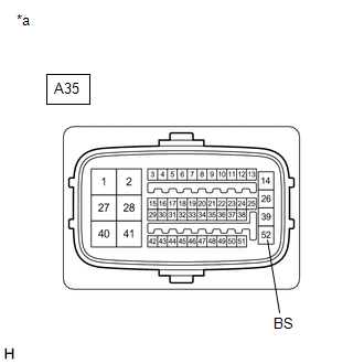
*a | Front view of wire harness connector
(to Skid Control ECU (Brake Booster with Master Cylinder Assembly)) | | |
(b) Make sure that there is no looseness at the locking part and the connecting part of the connector.
OK: The connector is securely connected. (c) Disconnect the A35 skid control ECU (brake booster with master cylinder assembly) connector.
(d) Check both the connector case and the terminals for deformation and corrosion.
OK: No deformation or corrosion. (e) Measure the voltage according to the value(s) in the table below.
Standard Voltage: |
Tester Connection | Condition |
Specified Condition | |
A35-52 (BS) - Body ground |
Always | 11 to 14 V |
| NG |
| REPAIR OR REPLACE HARNESS OR CONNECTOR (BS CIRCUIT) |
|
OK | |
| |
(a) Reconnect the A35 skid control ECU (brake booster with master cylinder assembly) connector.
(b) Clear the DTCs. Click here Chassis > ABS/VSC/TRAC > Clear DTCs
(c) Turn the power switch off. (d) Turn the power switch on (IG).
(e) Check if the same DTC is output. Click here
Chassis > ABS/VSC/TRAC > Trouble Codes
| Result |
Proceed to | | DTCs C1311 and C1312 are not output. |
A | | DTCs C1311 and/or C1312 are output. |
B |
| A |
| USE SIMULATION METHOD TO CHECK |
| B |
| REPLACE BRAKE BOOSTER WITH MASTER CYLINDER ASSEMBLY |
| 4. |
CHECK HARNESS AND CONNECTOR (+BI TERMINAL) |
| (a) Turn the power switch off. |
 |
|
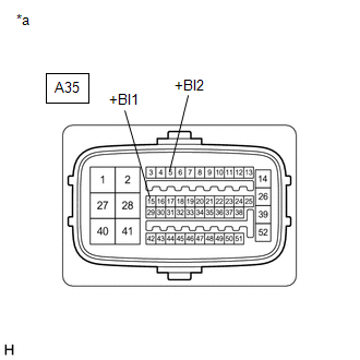
*a | Front view of wire harness connector
(to Skid Control ECU (Brake Booster with Master Cylinder Assembly)) | | |
(b) Make sure that there is no looseness at the locking part and the connecting part of the connector.
OK: The connector is securely connected. (c) Disconnect the A35 skid control ECU (brake booster with master cylinder assembly) connector.
(d) Check both the connector case and the terminals for deformation and corrosion.
OK: No deformation or corrosion. (e) Measure the voltage according to the value(s) in the table below.
Standard Voltage: |
Tester Connection | Condition |
Specified Condition | |
A35-15 (+BI1) - Body ground |
Always | 11 to 14 V | |
A35-5 (+BI2) - Body ground |
Always | 11 to 14 V |
| NG |
| REPAIR OR REPLACE HARNESS OR CONNECTOR (+BI CIRCUIT) |
|
OK | |
| |
| 5. |
CHECK HARNESS AND CONNECTOR (BS TERMINAL) |
| (a) Measure the voltage according to the value(s) in the table below.
Standard Voltage: |
Tester Connection | Condition |
Specified Condition | |
A35-52 (BS) - Body ground |
Always | 11 to 14 V | |
|
|
|
*a | Front view of wire harness connector
(to Skid Control ECU (Brake Booster with Master Cylinder Assembly)) | | |
| OK |
| REPLACE BRAKE BOOSTER WITH MASTER CYLINDER ASSEMBLY |
| NG |
| REPAIR OR REPLACE HARNESS OR CONNECTOR (BS CIRCUIT) | | 

