DESCRIPTION Each solenoid
adjusts the pressure which affects each wheel cylinder according to
signals from the skid control ECU (brake booster with master cylinder
assembly) and controls the vehicle. |
DTC No. | Detection Item |
INF Code | DTC Detection Condition |
Trouble Area | MIL |
Note | | C1352 |
Increasing Pressure Solenoid (FR) |
11 1100 1101 1102 1103 1170 |
- INF Code: 11
- A malfunction in the solenoid current monitoring circuit is detected for 0.05 seconds or more.
- INF Code: 1100
- An open is detected in the solenoid for 0.05 seconds or more.
- INF Code: 1101
- Overcurrent is detected in the solenoid for 0.05 seconds or more.
- INF Code: 1102
- Current leakage is detected in the solenoid for 0.05 seconds or more.
- INF Code: 1103
- A solenoid drive circuit malfunction (flyback diode malfunction) is detected for 0.05 seconds or more.
- INF Code: 1170
- The ECU solenoid output differs from the drain monitoring output (drain
monitoring is on when the ECU solenoid is not operating) for 0.05
seconds or more.
|
- Wire harness or connector
- Brake actuator assembly
- Skid control ECU (brake booster with master cylinder assembly)
| Comes on |
- INF Code 11: SAE Code C12BC (Case 2)
- INF Code 1100: SAE Code C12BD
- INF Code 1101: SAE Code C12BE (Case 1)
- INF Code 1102: SAE Code C12BE (Case 2)
- INF Code 1103: SAE Code C12BC (Case 1)
- INF Code 1170: SAE Code C12BE (Case 3)
- Electronically controlled brake system DTC
| | C1353 |
Increasing Pressure Solenoid (FL) |
13 1106 1107 1108 1109 1172 |
- INF Code: 13
- A malfunction in the solenoid current monitoring circuit is detected for 0.05 seconds or more.
- INF Code: 1106
- An open is detected in the solenoid for 0.05 seconds or more.
- INF Code: 1107
- Overcurrent is detected in the solenoid for 0.05 seconds or more.
- INF Code: 1108
- Current leakage is detected in the solenoid for 0.05 seconds or more.
- INF Code: 1109
- A solenoid drive circuit malfunction (flyback diode malfunction) is detected for 0.05 seconds or more.
- INF Code: 1172
- The ECU solenoid output differs from the drain monitoring output (drain
monitoring is on when the ECU solenoid is not operating) for 0.05
seconds or more.
|
- Wire harness or connector
- Brake actuator assembly
- Skid control ECU (brake booster with master cylinder assembly)
| Comes on |
- INF Code 13: SAE Code C12A6 (Case 2)
- INF Code 1106: SAE Code C12A7
- INF Code 1107: SAE Code C12A8 (Case 1)
- INF Code 1108: SAE Code C12A8 (Case 2)
- INF Code 1109: SAE Code C12A6 (Case 1)
- INF Code 1172: SAE Code C12A8 (Case 3)
- Electronically controlled brake system DTC
| | C1354 |
Increasing Pressure Solenoid (RR) |
15 1112 1113 1114 1115 1174 |
- INF Code: 15
- A malfunction in the solenoid current monitoring circuit is detected for 0.05 seconds or more.
- INF Code: 1112
- An open is detected in the solenoid for 0.05 seconds or more.
- INF Code: 1113
- Overcurrent is detected in the solenoid for 0.05 seconds or more.
- INF Code: 1114
- Current leakage is detected in the solenoid for 0.05 seconds or more.
- INF Code: 1115
- A solenoid drive circuit malfunction (flyback diode malfunction) is detected for 0.05 seconds or more.
- INF Code: 1174
- The ECU solenoid output differs from the drain monitoring output (drain
monitoring is on when the ECU solenoid is not operating) for 0.05
seconds or more.
|
- Wire harness or connector
- Brake actuator assembly
- Skid control ECU (brake booster with master cylinder assembly)
| Comes on |
- INF Code 15: SAE Code C12E8 (Case 2)
- INF Code 1112: SAE Code C12E9
- INF Code 1113: SAE Code C12EA (Case 1)
- INF Code 1114: SAE Code C12EA (Case 2)
- INF Code 1115: SAE Code C12E8 (Case 1)
- INF Code 1174: SAE Code C12EA (Case 3)
- Electronically controlled brake system DTC
| | C1355 |
Increasing Pressure Solenoid (RL) |
17 1118 1119 1120 1121 1176 |
- INF Code: 17
- A malfunction in the solenoid current monitoring circuit is detected for 0.05 seconds or more.
- INF Code: 1118
- An open is detected in the solenoid for 0.05 seconds or more.
- INF Code: 1119
- Overcurrent is detected in the solenoid for 0.05 seconds or more.
- INF Code: 1120
- Current leakage is detected in the solenoid for 0.05 seconds or more.
- INF Code: 1121
- A solenoid drive circuit malfunction (flyback diode malfunction) is detected for 0.05 seconds or more.
- INF Code: 1176
- The ECU solenoid output differs from the drain monitoring output (drain
monitoring is on when the ECU solenoid is not operating) for 0.05
seconds or more.
|
- Wire harness or connector
- Brake actuator assembly
- Skid control ECU (brake booster with master cylinder assembly)
| Comes on |
- INF Code 17: SAE Code C12D2 (Case 2)
- INF Code 1118: SAE Code C12D3
- INF Code 1119: SAE Code C12D4 (Case 1)
- INF Code 1120: SAE Code C12D4 (Case 2)
- INF Code 1121: SAE Code C12D2 (Case 1)
- INF Code 1176: SAE Code C12D4 (Case 3)
- Electronically controlled brake system DTC
| | C1356 |
Decreasing Pressure Solenoid (FR) |
12 1104 1105 1171 |
- INF Code: 12
- An open is detected in the solenoid for 0.05 seconds or more.
- INF Code: 1104
- Overcurrent is detected in the solenoid for 0.05 seconds or more.
- INF Code: 1105
- Current leakage is detected in the solenoid for 0.05 seconds or more.
- INF Code: 1171
- The ECU solenoid output differs from the drain monitoring output (drain
monitoring is on when the ECU solenoid is not operating) for 0.05
seconds or more.
|
- Wire harness or connector
- Brake actuator assembly
- Skid control ECU (brake booster with master cylinder assembly)
| Comes on |
- INF Code 12: SAE Code C12C8
- INF Code 1104: SAE Code C12C9 (Case 1)
- INF Code 1105: SAE Code C12C9 (Case 2)
- INF Code 1171: SAE Code C12C9 (Case 3)
- Electronically controlled brake system DTC
| | C1357 |
Decreasing Pressure Solenoid (FL) |
14 1110 1111 1173 |
- INF Code: 14
- An open is detected in the solenoid for 0.05 seconds or more.
- INF Code: 1110
- Overcurrent is detected in the solenoid for 0.05 seconds or more.
- INF Code: 1111
- Current leakage is detected in the solenoid for 0.05 seconds or more.
- INF Code: 1173
- The ECU solenoid output differs from the drain monitoring output (drain
monitoring is on when the ECU solenoid is not operating) for 0.05
seconds or more.
|
- Wire harness or connector
- Brake actuator assembly
- Skid control ECU (brake booster with master cylinder assembly)
| Comes on |
- INF Code 14: SAE Code C12B2
- INF Code 1110: SAE Code C12B3 (Case 1)
- INF Code 1111: SAE Code C12B3 (Case 2)
- INF Code 1173: SAE Code C12B3 (Case 3)
- Electronically controlled brake system DTC
| | C1358 |
Decreasing Pressure Solenoid (RR) |
16 1116 1117 1175 |
- INF Code: 16
- An open is detected in the solenoid for 0.05 seconds or more.
- INF Code: 1116
- Overcurrent is detected in the solenoid for 0.05 seconds or more.
- INF Code: 1117
- Current leakage is detected in the solenoid for 0.05 seconds or more.
- INF Code: 1175
- The ECU solenoid output differs from the drain monitoring output (drain
monitoring is on when the ECU solenoid is not operating) for 0.05
seconds or more.
|
- Wire harness or connector
- Brake actuator assembly
- Skid control ECU (brake booster with master cylinder assembly)
| Comes on |
- INF Code 16: SAE Code C12F4
- INF Code 1116: SAE Code C12F5 (Case 1)
- INF Code 1117: SAE Code C12F5 (Case 2)
- INF Code 1175: SAE Code C12F5 (Case 3)
- Electronically controlled brake system DTC
| | C1359 |
Decreasing Pressure Solenoid (RL) |
18 1122 1123 1177 |
- INF Code: 18
- An open is detected in the solenoid for 0.05 seconds or more.
- INF Code: 1122
- Overcurrent is detected in the solenoid for 0.05 seconds or more.
- INF Code: 1123
- Current leakage is detected in the solenoid for 0.05 seconds or more.
- INF Code: 1177
- The ECU solenoid output differs from the drain monitoring output (drain
monitoring is on when the ECU solenoid is not operating) for 0.05
seconds or more.
|
- Wire harness or connector
- Brake actuator assembly
- Skid control ECU (brake booster with master cylinder assembly)
| Comes on |
- INF Code 18: SAE Code C12DE
- INF Code 1122: SAE Code C12DF (Case 1)
- INF Code 1123: SAE Code C12DF (Case 2)
- INF Code 1177: SAE Code C12DF (Case 3)
- Electronically controlled brake system DTC
| MONITOR DESCRIPTION
The
skid control ECU (brake booster with master cylinder assembly) monitors
the drive voltage and current of the ABS holding solenoid and ABS
reduction solenoid. Based on the monitored information, if any of the
following abnormal conditions are detected, the MIL is illuminated and a
DTC is stored.
- A flyback circuit malfunction is detected.
- A malfunction of the current monitor is detected.
- An open circuit in the holding valve is detected.
- When the monitored current value increases to a value that is not possible when normal.
- A current leakage is detected.
- Output malfunction is detected when there is a solenoid off command.
- An open circuit in the decrease pressure valve is detected.
MONITOR STRATEGY |
Related DTCs | C12A6 (Case 1): ABS holding solenoid range/performance
C12A6 (Case 2): ABS holding solenoid range/performance C12A7: ABS holding solenoid circuit low
C12A8 (Case 1): ABS holding solenoid circuit high C12A8 (Case 2): ABS holding solenoid circuit high
C12A8 (Case 3): ABS holding solenoid circuit high C12B2: ABS reduction solenoid circuit low
C12B3 (Case 1): ABS reduction solenoid circuit high C12B3 (Case 2): ABS reduction solenoid circuit high
C12B3 (Case 3): ABS reduction solenoid circuit high C12BC (Case 1): ABS holding solenoid range/performance
C12BC (Case 2): ABS holding solenoid range/performance C12BD: ABS holding solenoid circuit low
C12BE (Case 1): ABS holding solenoid circuit high C12BE (Case 2): ABS holding solenoid circuit high
C12BE (Case 3): ABS holding solenoid circuit high C12C8: ABS reduction solenoid circuit low
C12C9 (Case 1): ABS reduction solenoid circuit high C12C9 (Case 2): ABS reduction solenoid circuit high
C12C9 (Case 3): ABS reduction solenoid circuit high C12D2 (Case 1): ABS holding solenoid range/performance
C12D2 (Case 2): ABS holding solenoid range/performance C12D3: ABS holding solenoid circuit low
C12D4 (Case 1): ABS holding solenoid circuit high C12D4 (Case 2): ABS holding solenoid circuit high
C12D4 (Case 3): ABS holding solenoid circuit high C12DE: ABS reduction solenoid circuit low
C12DF (Case 1): ABS reduction solenoid circuit high C12DF (Case 2): ABS reduction solenoid circuit high
C12DF (Case 3): ABS reduction solenoid circuit high C12E8 (Case 1): ABS holding solenoid range/performance
C12E8 (Case 2): ABS holding solenoid range/performance C12E9: ABS holding solenoid circuit low
C12EA (Case 1): ABS holding solenoid circuit high C12EA (Case 2): ABS holding solenoid circuit high
C12EA (Case 3): ABS holding solenoid circuit high C12F4: ABS reduction solenoid circuit low
C12F5 (Case 1): ABS reduction solenoid circuit high C12F5 (Case 2): ABS reduction solenoid circuit high
C12F5 (Case 3): ABS reduction solenoid circuit high | |
Required Sensors/Components(Main) | Skid control ECU (brake booster with master cylinder assembly)
Brake actuator assembly | | Required Sensors/Components(Related) |
Skid control ECU (brake booster with master cylinder assembly)
Brake actuator assembly | | Frequency of Operation |
Continuous | | Duration |
54 times: C12B2, C12C8, C12DE and C12F4 0.054
seconds: C12A6 (Case 1 and 2), C12A7, C12A8 (Case 1, 2 and 3), C12B3
(Case 1, 2 and 3), C12BC (Case 1 and 2), C12BD, C12BE (Case 1, 2 and 3),
C12C9 (Case 1, 2 and 3), C12D2 (Case 1 and 2), C12D3, C12D4 (Case 1, 2
and 3), C12DF (Case 1, 2 and 3), C12E8 (Case 1 and 2), C12E9, C12EA
(Case 1, 2 and 3) and C12F5 (Case 1, 2 and 3) | | MIL Operation |
Immediately | | Sequence of Operation |
None | TYPICAL ENABLING CONDITIONS All |
Monitor runs whenever the following DTCs are not stored |
None | C12A6, C12BC, C12D2 and C12E8 (Case 1 and 2) |
Serial communication with low side IC | Valid | C12A7, C12BD, C12D3 and C12E9 |
All of the following conditions are met | - | |
Power supply for ABS solenoid | Higher than 9.13 V | |
Serial communication with low side IC | Valid | |
Output duty cycle | Higher than 40% | |
ABS holding solenoid current monitor | Normal | |
ABS solenoid power supply relay | On | C12A8, C12B3, C12BE, C12C9, C12D4, C12DF, C12EA and C12F5 (Case 1) |
Both of the following conditions are met | - | |
Serial communication with low side IC | Valid | |
Current monitor power supply | Higher than 1.2 V, and less than 1.38 V | C12A8, C12BE, C12D4 and C12EA (Case 2) |
All of the following conditions are met | - | |
Serial communication with low side IC | Valid | |
ABS solenoid power supply relay | On | |
Output duty cycle | 0% | C12A8, C12BE, C12D4 and C12EA (Case 3) |
All of the following conditions are met | - | |
Serial communication with low side IC | Valid | |
Power supply for ABS solenoid | Higher than 9.13 V | |
Output duty cycle | 0% | | ABS solenoid power supply relay |
On | C12B2, C12C8, C12DE and C12F4 |
All of the following conditions are met | - | |
ABS solenoid power supply relay | On | |
Serial communication with low side IC | Valid | |
Command to reduction solenoid on/off | On | |
ABS reduction solenoid current | Less than 4.4 A | C12B3, C12C9, C12DF and C12F5 (Case 2) |
All of the following conditions are met | - | |
Serial communication with low side IC | Valid | |
ABS solenoid power supply relay | On | |
Command to reduction solenoid on/off | Off | C12B3, C12C9, C12DF and C12F5 (Case 3) |
All of the following conditions are met | - | |
Serial communication with low side IC | Valid | |
Power supply for ABS solenoid | Higher than 9.13 V | |
Command to reduction solenoid on/off | Off | |
ABS solenoid power supply relay | On | TYPICAL MALFUNCTION THRESHOLDS C12A6, C12BC, C12D2 and C12E8 (Case 1) |
ABS holding solenoid voltage | Higher than 35 V | C12A6, C12BC, C12D2 and C12E8 (Case 2) |
One of the following conditions is met | A, B or C | |
A. Both of the following conditions are met | - | |
ABS holding solenoid current monitor value | Less than 46 | |
ABS holding solenoid current | Less than 3.5 A | |
B. Current monitor power supply | Higher than 1.38 V, or less than 1.2 V | |
C. AC/DC converter built into CPU standard voltage |
Less than 4.4 V | C12A7, C12BD, C12D3 and C12E9 |
ABS holding solenoid current | Less than 0.2 A | C12A8, C12BE, C12D4 and C12EA (Case 1) |
ABS holding solenoid current | Higher than 3.5 A | C12A8, C12BE, C12D4 and C12EA (Case 2) |
ABS holding solenoid voltage | Less than 11.25 V | C12A8, C12BE, C12D4 and C12EA (Case 3) |
ABS holding solenoid voltage | Less than 4.128 V | C12B2, C12C8, C12DE and C12F4 |
Either of the following conditions is met | - | |
ABS reduction solenoid voltage | Higher than 4.2 V | |
ABS reduction solenoid current | Less than 0.02 A | C12B3, C12C9, C12DF and C12F5 (Case 1) |
ABS reduction solenoid current | Higher than 4.4 A | C12B3, C12C9, C12DF and C12F5 (Case 2) |
ABS reduction solenoid voltage | Less than 11.25 V | C12B3, C12C9, C12DF and C12F5 (Case 3) |
ABS reduction solenoid voltage | Less than 4.128 V | COMPONENT OPERATING RANGE C12A6, C12BC, C12D2 and C12E8 (Case 1) |
All of the following conditions are met | - | |
ABS solenoid power supply relay | On | |
Serial communication with low side IC | Valid | |
Output duty cycle | Higher than 0% | |
Low side IC malfunction | Not detected | |
ABS holding solenoid voltage | Less than 35 V | C12A6, C12BC, C12D2 and C12E8 (Case 2) |
All of the following conditions are met | - | |
ABS solenoid power supply relay | On | |
Serial communication with low side IC | Valid | |
ABS holding solenoid current monitor value | 46 or more | |
Current monitor power supply | 1.38 V or less, and 1.2 V or more | |
AC/DC converter built into CPU standard voltage |
Higher than 4.4 V | C12A7, C12BD, C12D3 and C12E9 |
All of the following conditions are met | - | |
ABS solenoid power supply relay | On | |
Serial communication with low side IC | Valid | |
Output duty cycle | Higher than 40% | |
ABS holding solenoid current monitor | Normal | |
ABS holding solenoid current | 0.2 A or more | C12A8, C12BE, C12D4 and C12EA (Case 1) |
All of the following conditions are met | - | |
ABS solenoid power supply relay | On | |
Serial communication with low side IC | Valid | |
Output duty cycle | Higher than 0% | |
Low side IC malfunction | Not detected | |
ABS holding solenoid current | Less than 3.5 A | C12A8, C12BE, C12D4 and C12EA (Case 2) |
All of the following conditions are met |
- | | Serial communication with low side IC |
Valid | | ABS solenoid power supply relay |
On | | Output duty cycle |
0% | | ABS holding solenoid voltage |
Higher than 11.29 V | C12A8, C12BE, C12D4 and C12EA (Case 3) |
All of the following conditions are met | - | |
Serial communication with low side IC | Valid | |
ABS solenoid power supply relay | On | |
Output duty cycle | 0% | |
ABS holding solenoid voltage | Higher than 4.2 V | C12B2, C12C8, C12DE and C12F4 |
All of the following conditions are met | - | |
ABS solenoid power supply relay | On | |
Serial communication with low side IC | Valid | |
Command to reduction solenoid on/off | On | |
Low side IC malfunction | Not detected | |
ABS reduction solenoid voltage | Less than 4.128 V | |
ABS reduction solenoid current | Higher than 0.02 A | C12B3, C12C9, C12DF and C12F5 (Case 1) |
All of the following conditions are met | - | |
ABS solenoid power supply relay | On | |
Serial communication with low side IC | Valid | |
Command to reduction solenoid on/off | On | |
Low side IC malfunction | Not detected | |
ABS reduction solenoid current | Less than 4.4 A | C12B3, C12C9, C12DF and C12F5 (Case 2) |
All of the following conditions are met |
- | | Serial communication with low side IC |
Valid | | ABS solenoid power supply relay |
On | | Command to reduction solenoid on/off |
Off | | ABS reduction solenoid voltage |
Higher than 11.29 V | C12B3, C12C9, C12DF and C12F5 (Case 3) |
All of the following conditions are met | - | |
Serial communication with low side IC | Valid | |
ABS solenoid power supply relay | On | |
Command to reduction solenoid on/off | Off | |
ABS reduction solenoid voltage | Higher than 4.2 V | CONFIRMATION DRIVING PATTERN
- Connect the Techstream to the DLC3.
- Turn the power switch on (IG).
- Turn the Techstream on.
- Clear the DTCs (even if no DTCs are stored, perform the clear DTC procedure).
- Turn the power switch off.
- Turn the power switch on (IG).
- Turn the Techstream on.
- Drive the vehicle at a speed of 20 km/h (12 mph) for 1 minute.
- Operate the ABS using a drum tester or equivalent.
- Enter the following menus: Chassis / ABS/VSC/TRAC / Trouble Codes.
- Read the DTCs.
HINT:
- If a DTC is output, the system is malfunctioning.
- If a DTC is not output, perform the following procedure.
- If the DTCs are not output, perform a universal trip and check for permanent DTCs.
Click here 
HINT:
- If a permanent DTC is output, the system is malfunctioning.
- If no permanent DTCs are output, the system is normal.
WIRING DIAGRAM
 CAUTION / NOTICE / HINT
NOTICE: After
replacing the skid control ECU (brake booster with master cylinder
assembly) or brake actuator assembly, perform linear solenoid valve
offset learning, ABS holding solenoid valve learning, yaw rate and
acceleration sensor zero point calibration and system information
memorization after performing "Reset Memory". Click here
PROCEDURE
| 1. |
INSPECT BRAKE ACTUATOR ASSEMBLY | (a) Make sure that there is no looseness at the locking part and the connecting part of the connector.
OK: The connector is securely connected.
|
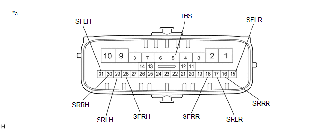
*a | Component without harness connected (Brake Actuator Assembly) |
- | - |
(b) Disconnect the A39 brake actuator assembly connector. (c) Check both the connector case and the terminals for deformation and corrosion.
OK: No deformation or corrosion. (d) Measure the resistance according to the value(s) in the table below.
HINT: Check the brake actuator assembly when it is cooled down.
Standard Resistance: |
Tester Connection | Condition |
Specified Condition | |
5 (+BS) - 28 (SFRH) | Always |
6.4 to 7.0 Ω | |
5 (+BS) - 31 (SFLH) | Always |
6.4 to 7.0 Ω | |
5 (+BS) - 30 (SRRH) | Always |
6.4 to 7.0 Ω | |
5 (+BS) - 29 (SRLH) | Always |
6.4 to 7.0 Ω | |
5 (+BS) - 18 (SFRR) | Always |
5.1 to 5.7 Ω | |
5 (+BS) - 15 (SFLR) | Always |
5.1 to 5.7 Ω | |
5 (+BS) - 16 (SRRR) | Always |
5.1 to 5.7 Ω | |
5 (+BS) - 17 (SRLR) | Always |
5.1 to 5.7 Ω |
| NG |
 | REPLACE BRAKE ACTUATOR ASSEMBLY |
|
OK |
 | |
| 2. |
CHECK HARNESS AND CONNECTOR (BRAKE BOOSTER WITH MASTER CYLINDER ASSEMBLY - BRAKE ACTUATOR ASSEMBLY) |
(a) Make sure that there is no looseness at the locking part and the connecting part of the connector.
OK: The connector is securely connected. (b) Disconnect the A35 skid control ECU (brake booster with master cylinder assembly) connector.
(c) Check both the connector case and the terminals for deformation and corrosion.
OK: No deformation or corrosion. (d) Measure the resistance according to the value(s) in the table below.
Standard Resistance: |
Tester Connection | Condition |
Specified Condition | |
A35-14 (+BS) - A39-5 (+BS) |
Always | Below 1 Ω | |
A35-14 (+BS) or A39-5 (+BS) - Body ground |
Always | 10 kΩ or higher | |
A35-48 (SFRH) - A39-28 (SFRH) |
Always | Below 1 Ω | |
A35-48 (SFRH) or A39-28 (SFRH) - Body ground |
Always | 10 kΩ or higher | |
A35-49 (SFLH) - A39-31 (SFLH) |
Always | Below 1 Ω | |
A35-49 (SFLH) or A39-31 (SFLH) - Body ground |
Always | 10 kΩ or higher | |
A35-50 (SRRH) - A39-30 (SRRH) |
Always | Below 1 Ω | |
A35-50 (SRRH) or A39-30 (SRRH) - Body ground |
Always | 10 kΩ or higher | |
A35-51 (SRLH) - A39-29 (SRLH) |
Always | Below 1 Ω | |
A35-51 (SRLH) or A39-29 (SRLH) - Body ground |
Always | 10 kΩ or higher | |
A35-44 (SFRR) - A39-18 (SFRR) |
Always | Below 1 Ω | |
A35-44 (SFRR) or A39-18 (SFRR) - Body ground |
Always | 10 kΩ or higher | |
A35-45 (SFLR) - A39-15 (SFLR) |
Always | Below 1 Ω | |
A35-45 (SFLR) or A39-15 (SFLR) - Body ground |
Always | 10 kΩ or higher | |
A35-46 (SRRR) - A39-16 (SRRR) |
Always | Below 1 Ω | |
A35-46 (SRRR) or A39-16 (SRRR) - Body ground |
Always | 10 kΩ or higher | |
A35-47 (SRLR) - A39-17 (SRLR) |
Always | Below 1 Ω | |
A35-47 (SRLR) or A39-17 (SRLR) - Body ground |
Always | 10 kΩ or higher |
| NG |
| REPAIR OR REPLACE HARNESS OR CONNECTOR |
|
OK | |
| |
(a) Reconnect the A35 skid control ECU (brake booster with master cylinder assembly) connector.
(b) Reconnect the A39 brake actuator assembly connector. (c) Clear the DTCs.
Click here Chassis > ABS/VSC/TRAC > Clear DTCs
(d) Turn the power switch off. (e) Turn the power switch on (IG).
(f) Check if the same DTC is output. Click here
Chassis > ABS/VSC/TRAC > Trouble Codes
|
Result | Proceed to | |
DTCs C1352, C1353, C1354, C1355, C1356, C1357, C1358 and C1359 are not output. |
A | | DTCs C1352, C1353, C1354, C1355, C1356, C1357, C1358 and/or C1359 are output. |
B |
| A |
| USE SIMULATION METHOD TO CHECK |
| B |
| REPLACE BRAKE BOOSTER WITH MASTER CYLINDER ASSEMBLY | |


