DESCRIPTION Refer to DTCs C1415 and C1416. Click here
 |
DTC No. | Detection Item |
INF Code | DTC Detection Condition |
Trouble Area | MIL |
Note | | C1403 |
Malfunction in Rear Speed Sensor RH Circuit |
521 522 527 |
- INF Code: 521
- At a vehicle speed of 10 km/h (6 mph) or more, output voltage from one
of the speed sensors is less than that from the other sensors for 15
seconds or more.
- INF Code: 522
- At a vehicle speed of 10 km/h (6 mph) or more, outputs from both speed
sensors are 0 km/h (0 mph) for 15 seconds or more. (except when both
rear speed sensors are 0 km/h (0 mph)).
- INF Code: 527
- At a vehicle speed of 10 km/h (6 mph) or more, output from one of the speed sensors is 0 km/h (0 mph) for 1 second or more.
|
- Skid control sensor wire RH (No. 1 parking brake wire assembly)
- Rear speed sensor RH (rear axle hub and bearing assembly RH)
- Speed sensor installed improperly
- Rear speed sensor rotor RH (rear axle hub and bearing assembly RH)
- Wire harness or connector
| Comes on |
- INF Code 521: SAE Code C0513 (Case 1)
- INF Code 522: SAE Code C140E
- INF Code 527: SAE Code C0513 (Case 2)
- ABS DTC
| | C1404 |
Malfunction in Rear Speed Sensor LH Circuit |
531 532 537 |
- INF Code: 531
- At a vehicle speed of 10 km/h (6 mph) or more, output voltage from one
of the speed sensors is less than that from the other sensors for 15
seconds or more.
- INF Code: 532
- At a vehicle speed of 10 km/h (6 mph) or more, outputs from both speed
sensors are 0 km/h (0 mph) for 15 seconds or more. (except when both
rear speed sensors are 0 km/h (0 mph)).
- INF Code: 537
- At a vehicle speed of 10 km/h (6 mph) or more, output from one of the speed sensors is 0 km/h (0 mph) for 1 second or more.
|
- Skid control sensor wire LH (No. 2 parking brake wire assembly)
- Rear speed sensor LH (rear axle hub and bearing assembly LH)
- Speed sensor installed improperly
- Rear speed sensor rotor LH (rear axle hub and bearing assembly LH)
- Wire harness or connector
| Comes on |
- INF Code 531: SAE Code C050D (Case 1)
- INF Code 532: SAE Code C140D
- INF Code 537: SAE Code C050D (Case 2)
- ABS DTC
| MONITOR DESCRIPTION
When
the vehicle is being driven, if the value of the speed sensor which is
outputting the lowest vehicle speed is significantly lower than the
values of the other speed sensors, or the value of the speed sensor
which is outputting the lowest vehicle speed is 0 km/h (0 mph), the skid
control ECU (brake booster with master cylinder assembly) judges that
the speed sensor is malfunctioning and illuminates the MIL and stores a
DTC. Also, when a wheel speed is being output
(the wheel is not locked), if the output values of the speed sensors for
2 wheels are stuck at 0 km/h (0 mph), the skid control ECU (brake
booster with master cylinder assembly) judges that a speed sensor is
malfunctioning and illuminates the MIL and stores a DTC. MONITOR STRATEGY |
Related DTCs | C050D (Case 1): Speed sensor range/performance
C050D (Case 2): Speed sensor range/performance C0513 (Case 1): Speed sensor range/performance
C0513 (Case 2): Speed sensor range/performance C140D: 2 wheel speed sensors malfunction
C140E: 2 wheel speed sensors malfunction | |
Required Sensors/Components(Main) | Speed sensor
Speed sensor rotor | | Required Sensors/Components(Related) |
Stop light switch assembly Parking brake ECU (brake actuator assembly)
Brake actuator (brake booster with master cylinder assembly) Speed sensor | |
Frequency of Operation | Continuous | |
Duration | 1 second: C050D (Case 2) and C0513 (Case 2)
15 seconds: C050D (Case 1), C0513 (Case 1), C140D and C140E | |
MIL Operation | Immediately | |
Sequence of Operation | None | TYPICAL ENABLING CONDITIONS C050D and C0513 (Case 1) |
Monitor runs whenever the following DTCs are not stored |
C0502, C0508, C050E, C0514 (Speed sensor circuit low) C0503, C0509, C050F, C0515 (Speed sensor circuit high)
C0504, C050A, C0510, C0516 (Speed sensor intermittent/erratic) C051C (Case 1) (Acceleration sensor range/performance)
C051C (Case 2) (Acceleration sensor range/performance) C051C (Case 3) (Acceleration sensor range/performance)
C051C (Case 4) (Acceleration sensor range/performance) C051E (Acceleration sensor intermittent/erratic)
C0520 (Case 1) (Acceleration sensor 2 out of range) C0520 (Case 2) (Acceleration sensor 1 and acceleration sensor 2 out of range)
C0520 (Case 3) (Acceleration sensor internal malfunction) C052B (ABS pump motor range/performance)
C052D (ABS pump motor circuit high) C052E (ABS pump motor open circuit)
C0562 (Brake pedal stroke sensor assembly voltage circuit/open) C0594 (Pump motor performance)
C0597 (EEPROM malfunction) C0597 (Lost communication) C0597 (CPU malfunction)
C0597 (IC malfunction) C1202 (Brake master cylinder reservoir assembly level too low)
C120F (Brake fluid level warning switch open circuit) C121D (Pump motor open circuit)
C121E (Pump motor circuit high) C123B (IG1 circuit low) C123E (IG2 circuit low)
C1240 (Yaw rate and acceleration sensor incorrect) C1241 (Brake system voltage circuit low)
C1241 (Speed sensor voltage circuit low) C124A (CAN communication identification signal)
C124B (Brake pedal stroke sensor assembly invalid data) C1256 (Accumulator pressure too low)
C12A6, C12BC, C12D2, C12E8 (ABS holding solenoid range/performance)
C12A7, C12BD, C12D3, C12E9 (ABS holding solenoid circuit low) C12A8, C12BE, C12D4, C12EA (ABS holding solenoid circuit high)
C12B2, C12C8, C12DE, C12F4 (ABS reduction solenoid circuit low) C12B3, C12C9, C12DF, C12F5 (ABS reduction solenoid circuit high)
C12FA (Main relay circuit low) C12FB (Main relay circuit high)
C1336 (Acceleration sensor exceeded learning limit) C1392 (Brake pedal stroke sensor learning not complete)
C139A (One hydraulic path fail) C139D (Linear solenoid (SLA) stuck on)
C13C1, C13CA, C14F2, C14FB (Linear solenoid range/performance) C13C2, C13CB, C14F3, C14FC (Linear solenoid circuit low)
C13C3, C13CC, C14F4, C14FD (Linear solenoid circuit high) C13CD (Brake pressure too low)
C13CE (Brake pressure too high) C1400 (ABS reduction solenoid leakage)
C140B, C140C, C140D, C140E (2 wheel speed sensors malfunction) C1417 (Brake system voltage circuit high)
C1427 (ABS pump motor stuck) C1451 (High pressure hydraulic tube air bleeding not complete)
C146E (ABS solenoid power supply relay circuit low) C146F (ABS solenoid power supply relay circuit high)
C14B0 (Reaction force pressure sensor voltage circuit check) C14B1 (Reaction force pressure sensor lost communication)
C14B2 (Reaction force pressure sensor internal malfunction) C14B3 (Reaction force pressure sensor exceeded learning limit)
C14B4 (Reaction force pressure sensor intermittent/erratic) C14B5 (Reaction force pressure sensor invalid data)
C14B6 (Brake stroke/reaction force pressure correlation) C14C0 (Servo pressure sensor voltage circuit check)
C14C1 (Servo pressure sensor lost communication) C14C2 (Servo pressure sensor internal malfunction)
C14C3 (Servo pressure sensor exceeded learning limit) C14C4 (Servo pressure sensor intermittent/erratic)
C14C5 (Servo pressure sensor invalid data) C14D0 (Accumulator pressure sensor voltage circuit check)
C14D1 (Accumulator pressure sensor lost communication) C14D2 (Accumulator pressure sensor internal malfunction)
C14D3 (Accumulator pressure sensor intermittent/erratic) C14D4 (Case 1) (Accumulator pressure sensor invalid data)
C14D4 (Case 2) (Accumulator pressure sensor intermittent) C14D5 (Accumulator pressure sensor stuck)
C14D7 (Acceleration sensor voltage circuit/open) C14DB (ABS solenoid power supply voltage circuit low)
C14DE (Main relay voltage circuit low) C14DF (Main relay voltage circuit high)
C14E1, C14E4, C14E7, C14EA (Case 1) (Speed sensor voltage circuit low)
C14E1, C14E4, C14E7, C14EA (Case 2) (Speed sensor voltage circuit low)
C14EE (Switching solenoid (SSA) stuck on) C14F7 (Switching solenoid (SGH) stuck on)
P0572 (Stop light switch assembly open circuit) P0573 (Stop light switch assembly circuit high)
P057C, P05DD (Brake pedal stroke sensor assembly open circuit) P057D, P05DE (Brake pedal stroke sensor assembly circuit high)
P057E, P05DF (Brake pedal stroke sensor assembly intermittent/erratic)
P05E0 (Brake pedal stroke sensor assembly "1"/"2" correlation) U0073 (Control module communication bus "A" off)
U0074 (Control module communication bus "B" off) U0100 (Case 1) (Lost communication with ECM/PCM "A")
U0110 (Case 1) (Lost communication with drive motor control module "A")
U0125 (Lost communication with multi-axis acceleration sensor module)
U0293 (Case 1) (Lost communication with hybrid powertrain control module) | |
All of the following conditions are met |
- | | Control valve solenoid |
Non-drive | | Brake system voltage 1 (VM1) |
Less than 16.44 V | | Difference between the highest speed sensor output value and the second lowest speed sensor output value |
Less than 20% of the highest speed sensor output value | |
The second lowest speed sensor output value |
10 km/h (6 mph) or more | | Speed
sensor fail (C0502, C0503, C0504, C0508, C0509, C050A, C050E, C050F,
C0510, C0514, C0515, C0516, C14E1, C14E4, C14E7, C14EA) |
Not detected | C050D and C0513 (Case 2) |
Monitor runs whenever the following DTCs are not stored |
C0502, C0508, C050E, C0514 (Speed sensor circuit low) C0503, C0509, C050F, C0515 (Speed sensor circuit high)
C0504, C050A, C0510, C0516 (Speed sensor intermittent/erratic) C051C (Case 1) (Acceleration sensor range/performance)
C051C (Case 2) (Acceleration sensor range/performance) C051C (Case 3) (Acceleration sensor range/performance)
C051C (Case 4) (Acceleration sensor range/performance) C051E (Acceleration sensor intermittent/erratic)
C0520 (Case 1) (Acceleration sensor 2 out of range) C0520 (Case 2) (Acceleration sensor 1 and acceleration sensor 2 out of range)
C0520 (Case 3) (Acceleration sensor internal malfunction) C052B (ABS pump motor range/performance)
C052D (ABS pump motor circuit high) C052E (ABS pump motor open circuit)
C0562 (Brake pedal stroke sensor assembly voltage circuit/open) C0594 (Pump motor performance)
C0597 (EEPROM malfunction) C0597 (Lost communication) C0597 (CPU malfunction)
C0597 (IC malfunction) C1202 (Brake master cylinder reservoir assembly level too low)
C120F (Brake fluid level warning switch open circuit) C121D (Pump motor open circuit)
C121E (Pump motor circuit high) C123B (IG1 circuit low) C123E (IG2 circuit low)
C1240 (Yaw rate and acceleration sensor incorrect) C1241 (Brake system voltage circuit low)
C1241 (Speed sensor voltage circuit low) C124A (CAN communication identification signal)
C124B (Brake pedal stroke sensor assembly invalid data) C1256 (Accumulator pressure too low)
C12A6, C12BC, C12D2, C12E8 (ABS holding solenoid range/performance)
C12A7, C12BD, C12D3, C12E9 (ABS holding solenoid circuit low) C12A8, C12BE, C12D4, C12EA (ABS holding solenoid circuit high)
C12B2, C12C8, C12DE, C12F4 (ABS reduction solenoid circuit low) C12B3, C12C9, C12DF, C12F5 (ABS reduction solenoid circuit high)
C12FA (Main relay circuit low) C12FB (Main relay circuit high)
C1336 (Acceleration sensor exceeded learning limit) C1392 (Brake pedal stroke sensor learning not complete)
C139A (One hydraulic path fail) C139D (Linear solenoid (SLA) stuck on)
C13C1, C13CA, C14F2, C14FB (Linear solenoid range/performance) C13C2, C13CB, C14F3, C14FC (Linear solenoid circuit low)
C13C3, C13CC, C14F4, C14FD (Linear solenoid circuit high) C13CD (Brake pressure too low)
C13CE (Brake pressure too high) C1400 (ABS reduction solenoid leakage)
C140B, C140C, C140D, C140E (2 wheel speed sensors malfunction) C1417 (Brake system voltage circuit high)
C1427 (ABS pump motor stuck) C1451 (High pressure hydraulic tube air bleeding not complete)
C146E (ABS solenoid power supply relay circuit low) C146F (ABS solenoid power supply relay circuit high)
C14B0 (Reaction force pressure sensor voltage circuit check) C14B1 (Reaction force pressure sensor lost communication)
C14B2 (Reaction force pressure sensor internal malfunction) C14B3 (Reaction force pressure sensor exceeded learning limit)
C14B4 (Reaction force pressure sensor intermittent/erratic) C14B5 (Reaction force pressure sensor invalid data)
C14B6 (Brake stroke/reaction force pressure correlation) C14C0 (Servo pressure sensor voltage circuit check)
C14C1 (Servo pressure sensor lost communication) C14C2 (Servo pressure sensor internal malfunction)
C14C3 (Servo pressure sensor exceeded learning limit) C14C4 (Servo pressure sensor intermittent/erratic)
C14C5 (Servo pressure sensor invalid data) C14D0 (Accumulator pressure sensor voltage circuit check)
C14D1 (Accumulator pressure sensor lost communication) C14D2 (Accumulator pressure sensor internal malfunction)
C14D3 (Accumulator pressure sensor intermittent/erratic) C14D4 (Case 1) (Accumulator pressure sensor invalid data)
C14D4 (Case 2) (Accumulator pressure sensor intermittent) C14D5 (Accumulator pressure sensor stuck)
C14D7 (Acceleration sensor voltage circuit/open) C14DB (ABS solenoid power supply voltage circuit low)
C14DE (Main relay voltage circuit low) C14DF (Main relay voltage circuit high)
C14E1, C14E4, C14E7, C14EA (Case 1) (Speed sensor voltage circuit low)
C14E1, C14E4, C14E7, C14EA (Case 2) (Speed sensor voltage circuit low)
C14EE (Switching solenoid (SSA) stuck on) C14F7 (Switching solenoid (SGH) stuck on)
P0572 (Stop light switch assembly open circuit) P0573 (Stop light switch assembly circuit high)
P057C, P05DD (Brake pedal stroke sensor assembly open circuit) P057D, P05DE (Brake pedal stroke sensor assembly circuit high)
P057E, P05DF (Brake pedal stroke sensor assembly intermittent/erratic)
P05E0 (Brake pedal stroke sensor assembly "1"/"2" correlation) U0073 (Control module communication bus "A" off)
U0074 (Control module communication bus "B" off) U0100 (Case 1) (Lost communication with ECM/PCM "A")
U0110 (Case 1) (Lost communication with drive motor control module "A")
U0125 (Lost communication with multi-axis acceleration sensor module)
U0293 (Case 1) (Lost communication with hybrid powertrain control module) | |
All of the following conditions are met |
- | | Control valve solenoid |
Non-drive | | Brake system voltage 1 (VM1) |
Less than 16.44 V | |
Stop light switch assembly |
Off | | Parking brake |
Off | | Difference between the highest speed sensor output value and the second lowest speed sensor output value |
Less than 2 km/h (1 mph) | | The second lowest speed sensor output value |
10 km/h (6 mph) or more | | Speed
sensor fail (C0502, C0503, C0504, C0508, C0509, C050A, C050E, C050F,
C0510, C0514, C0515, C0516, C14E1, C14E4, C14E7, C14EA) |
Not detected | C140D and C140E |
Monitor runs whenever the following DTCs are not stored |
C0502, C0508, C050E, C0514 (Speed sensor circuit low) C0503, C0509, C050F, C0515 (Speed sensor circuit high)
C0504, C050A, C0510, C0516 (Speed sensor intermittent/erratic) C14E1, C14E4, C14E7, C14EA (Case 1) (Speed sensor voltage circuit low)
C14E1, C14E4, C14E7, C14EA (Case 2) (Speed sensor voltage circuit low) | |
All of the following conditions are met | - | |
Control valve solenoid | Non-drive | |
Brake system voltage 1 (VM1) | Less than 16.44 V | |
Stop light switch assembly | Off | |
Parking brake | Off | |
Difference
in output of the speed sensor with the highest value and the output of
the speed sensor with the second highest value. |
Less than 20% of the highest speed sensor output value | |
The second highest speed sensor output value |
10 km/h (6 mph) or more | | Speed
sensor fail (C0502, C0503, C0504, C0508, C0509, C050A, C050E, C050F,
C0510, C0514, C0515, C0516, C14E1, C14E4, C14E7, C14EA) |
Not detected | | Stop light switch assembly fail (P0572) |
Not detected | TYPICAL MALFUNCTION THRESHOLDS C050D and C0513 (Case 1) |
One-seventh of the second lowest speed sensor output value |
Higher than the lowest speed sensor output value | C050D and C0513 (Case 2) |
The lowest speed sensor output value | 0 km/h (0 mph) | C140D and C140E |
The second lowest speed sensor output value |
0 km/h (0 mph) | COMPONENT OPERATING RANGE C050D and C0513 (Case 1) |
All of the following conditions are met |
- | | Control valve solenoid |
Non-drive | | Brake system voltage 1 (VM1) |
Less than 16.44 V | | Difference between the highest speed sensor output value and the second lowest speed sensor output value |
Less than 20% of the highest speed sensor output value | |
The second lowest speed sensor output value |
10 km/h (6 mph) or more | | Speed
sensor fail (C0502, C0503, C0504, C0508, C0509, C050A, C050E, C050F,
C0510, C0514, C0515, C0516, C14E1, C14E4, C14E7, C14EA) |
Not detected | |
Speed sensor pass flag |
On | C050D and C0513 (Case 2) |
All of the following conditions are met |
- | | Control valve solenoid |
Non-drive | | Brake system voltage 1 (VM1) |
Less than 16.44 V | |
Stop light switch assembly |
Off | | Parking brake |
Off | | Difference between the highest speed sensor output value and the second lowest speed sensor output value |
Less than 2 km/h (1 mph) | | The second lowest speed sensor output value |
10 km/h (6 mph) or more | | Speed
sensor fail (C0502, C0503, C0504, C0508, C0509, C050A, C050E, C050F,
C0510, C0514, C0515, C0516, C14E1, C14E4, C14E7, C14EA) |
Not detected | |
Speed sensor pass flag |
On | C140D and C140E |
All of the following conditions are met | - | |
Control valve solenoid | Non-drive | |
Brake system voltage 1 (VM1) | Less than 16.44 V | |
Stop light switch assembly | Off | |
Parking brake | Off | |
Difference
in output of the speed sensor with the highest value and the output of
the speed sensor with the second highest value. |
Less than 20% of the highest speed sensor output value | |
The second highest speed sensor output value |
10 km/h (6 mph) or more | | Speed
sensor fail (C0502, C0503, C0504, C0508, C0509, C050A, C050E, C050F,
C0510, C0514, C0515, C0516, C14E1, C14E4, C14E7, C14EA) |
Not detected | | Stop light switch assembly fail (P0572) |
Not detected | |
Speed sensor pass flag |
On | CONFIRMATION DRIVING PATTERN
- Connect the Techstream to the DLC3.
- Turn the power switch on (IG).
- Turn the Techstream on.
- Clear the DTCs (even if no DTCs are stored, perform the clear DTC procedure).
- Turn the power switch off.
- Turn the power switch on (IG).
- Turn the Techstream on.
- Drive the vehicle straight at a speed of 15 km/h (9 mph) or more for 15 seconds or more.
- Enter the following menus: Chassis / ABS/VSC/TRAC / Trouble Codes.
- Read the DTCs.
HINT:
- If a DTC is output, the system is malfunctioning.
- If a DTC is not output, perform the following procedure.
- If the DTCs are not output, perform a universal trip and check for permanent DTCs.
Click here
HINT:
- If a permanent DTC is output, the system is malfunctioning.
- If no permanent DTCs are output, the system is normal.
WIRING DIAGRAM Refer to DTCs C1415 and C1416.
Click here PROCEDURE
(a) Clear the DTCs. Click here
Chassis > ABS/VSC/TRAC > Clear DTCs
(b) Turn the power switch off. (c) Turn the power switch on (IG).
(d) Check if the same DTC is output. Click here
Chassis > ABS/VSC/TRAC > Trouble Codes
| Result |
Proceed to | | DTC C1403 is output. |
A | | DTC C1404 is output. |
B |
| B |
 | GO TO STEP 6 |
|
A |
 | |
| 2. |
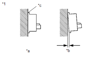
CHECK REAR SPEED SENSOR RH INSTALLATION |
| (a) Check the rear speed sensor RH installation. OK: There is no clearance between the sensor and the rear axle hub.
HINT: Because
the rear axle hub and bearing assembly RH cannot be disassembled, if
the rear speed sensor RH needs replacement, replace the rear axle hub
and bearing assembly RH. |
 |
|
*1 | Rear Speed Sensor RH | |
*a | OK | |
*b | NG | |
*c | No Clearance | | |
| NG |
| REPLACE REAR AXLE HUB AND BEARING ASSEMBLY RH |
|
OK | |
| |
| 3. |
READ VALUE USING TECHSTREAM (REAR SPEED SENSOR RH) |
(a) Select the Data List on the Techstream. Click here
Chassis > ABS/VSC/TRAC > Data List
|
Tester Display | Measurement Item |
Range | Normal Condition |
Diagnostic Note | |
RR Wheel Speed | Rear speed sensor RH |
Min.: 0 km/h (0 mph), Max.: 326.4 km/h (203 mph) |
Vehicle stopped: 0 km/h (0 mph) |
When driving at constant speed: No large fluctuations | Chassis > ABS/VSC/TRAC > Data List
|
Tester Display | | RR Wheel Speed |
(b) Check the rear speed sensor RH output value. OK: The output value changes in accordance with the vehicle speed.
| OK |
| USE SIMULATION METHOD TO CHECK |
|
NG | |
| |
| 4. |
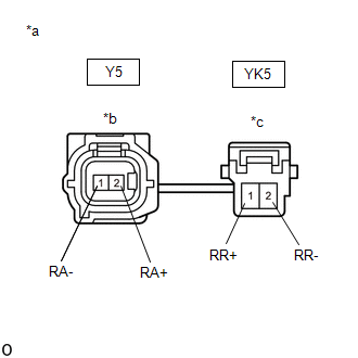
INSPECT NO. 1 PARKING BRAKE WIRE ASSEMBLY |
| (a) Turn the power switch off. |
 |
|
*a | Front view of skid control sensor wire RH (No. 1 parking brake wire assembly) | |
*b | Front view of wire harness connector
(to Sensor Side Connector) | |
*c | Front view of wire harness connector
(to Vehicle Side Connector) | | |
(b) Make sure that there is no looseness at the locking part and the connecting part of the connectors.
OK: The connector is securely connected. (c) Disconnect the Y5 and YK5 skid control sensor wire RH (No. 1 parking brake wire assembly) connectors.
(d) Check both the connector case and the terminals for deformation and corrosion.
OK: No deformation or corrosion. (e) Measure the resistance according to the value(s) in the table below.
Standard Resistance: |
Tester Connection | Condition |
Specified Condition | |
Y5-2 (RA+) - YK5-1 (RR+) |
Always | Below 1 Ω | |
Y5-2 (RA+) or YK5-1 (RR+) - Body ground and other terminals |
Always | 10 kΩ or higher | |
Y5-1 (RA-) - YK5-2 (RR-) |
Always | Below 1 Ω | |
Y5-1 (RA-) or YK5-2 (RR-) - Body ground and other terminals |
Always | 10 kΩ or higher |
| NG |
| REPLACE NO. 1 PARKING BRAKE WIRE ASSEMBLY |
|
OK | |
| |
| 5. |
CHECK HARNESS AND CONNECTOR (BRAKE BOOSTER WITH MASTER CYLINDER ASSEMBLY - NO. 1 PARKING BRAKE WIRE ASSEMBLY) |
(a) Make sure that there is no looseness at the locking part and the connecting part of the connector.
OK: The connector is securely connected. (b) Disconnect the A35 skid control ECU (brake booster with master cylinder assembly) connector.
(c) Check both the connector case and the terminals for deformation and corrosion.
OK: No deformation or corrosion. (d) Measure the resistance according to the value(s) in the table below.
Standard Resistance: |
Tester Connection | Condition |
Specified Condition | |
A35-7 (RR+) - YK5-1 (RR+) |
Always | Below 1 Ω | |
A35-7 (RR+) or YK5-1 (RR+) - Body ground |
Always | 10 kΩ or higher | |
A35-8 (RR-) - YK5-2 (RR-) |
Always | Below 1 Ω | |
A35-8 (RR-) or YK5-2 (RR-) - Body ground |
Always | 10 kΩ or higher |
NOTICE: Check the rear speed sensor RH signal after replacement.
Click here HINT: The rear speed sensor RH and rear speed sensor rotor RH are incorporated into the rear axle hub and bearing assembly RH.
If
the rear speed sensor RH and rear speed sensor rotor RH need to be
replaced, replace the rear axle hub and bearing assembly RH.
| OK |
| REPLACE REAR AXLE HUB AND BEARING ASSEMBLY RH |
| NG |
| REPAIR OR REPLACE HARNESS OR CONNECTOR |
| 6. |
CHECK REAR SPEED SENSOR LH INSTALLATION |
| (a) Check the rear speed sensor LH installation. OK: There is no clearance between the sensor and the rear axle hub.
HINT: Because
the rear axle hub and bearing assembly LH cannot be disassembled, if
the rear speed sensor LH needs replacement, replace the rear axle hub
and bearing assembly LH. | |
|
|
*1 | Rear Speed Sensor LH | |
*a | OK | |
*b | NG | |
*c | No Clearance | | |
| NG |
| REPLACE REAR AXLE HUB AND BEARING ASSEMBLY LH |
|
OK | |
| |
| 7. |
READ VALUE USING TECHSTREAM (REAR SPEED SENSOR LH) |
(a) Select the Data List on the Techstream. Click here
Chassis > ABS/VSC/TRAC > Data List
|
Tester Display | Measurement Item |
Range | Normal Condition |
Diagnostic Note | |
RL Wheel Speed | Rear speed sensor LH |
Min.: 0 km/h (0 mph), Max.: 326.4 km/h (203 mph) |
Vehicle stopped: 0 km/h (0 mph) |
When driving at constant speed: No large fluctuations | Chassis > ABS/VSC/TRAC > Data List
|
Tester Display | | RL Wheel Speed |
(b) Check the rear speed sensor LH output value. OK: The output value changes in accordance with the vehicle speed.
| OK |
| USE SIMULATION METHOD TO CHECK |
|
NG | |
| |
| 8. |
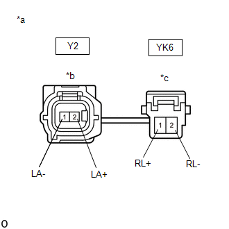
INSPECT NO. 2 PARKING BRAKE WIRE ASSEMBLY |
| (a) Turn the power switch off. |
 |
|
*a | Front view of skid control sensor wire LH (No. 2 parking brake wire assembly) | |
*b | Front view of wire harness connector
(to Sensor Side Connector) | |
*c | Front view of wire harness connector
(to Vehicle Side Connector) | | |
(b) Make sure that there is no looseness at the locking part and the connecting part of the connectors.
OK: The connector is securely connected. (c) Disconnect the Y2 and YK6 skid control sensor wire LH (No. 2 parking brake wire assembly) connectors.
(d) Check both the connector case and the terminals for deformation and corrosion.
OK: No deformation or corrosion. (e) Measure the resistance according to the value(s) in the table below.
Standard Resistance: |
Tester Connection | Condition |
Specified Condition | |
Y2-2 (LA+) - YK6-1 (RL+) |
Always | Below 1 Ω | |
Y2-2 (LA+) or YK6-1 (RL+) - Body ground and other terminals |
Always | 10 kΩ or higher | |
Y2-1 (LA-) - YK6-2 (RL-) |
Always | Below 1 Ω | |
Y2-1 (LA-) or YK6-2 (RL-) - Body ground and other terminals |
Always | 10 kΩ or higher |
| NG |
| REPLACE NO. 2 PARKING BRAKE WIRE ASSEMBLY |
|
OK | |
| |
| 9. |
CHECK HARNESS AND CONNECTOR (BRAKE BOOSTER WITH MASTER CYLINDER ASSEMBLY - NO. 2 PARKING BRAKE WIRE ASSEMBLY) |
(a) Make sure that there is no looseness at the locking part and the connecting part of the connector.
OK: The connector is securely connected. (b) Disconnect the A35 skid control ECU (brake booster with master cylinder assembly) connector.
(c) Check both the connector case and the terminals for deformation and corrosion.
OK: No deformation or corrosion. (d) Measure the resistance according to the value(s) in the table below.
Standard Resistance: |
Tester Connection | Condition |
Specified Condition | |
A35-34 (RL+) - YK6-1 (RL+) |
Always | Below 1 Ω | |
A35-34 (RL+) or YK6-1 (RL+) - Body ground |
Always | 10 kΩ or higher | |
A35-35 (RL-) - YK6-2 (RL-) |
Always | Below 1 Ω | |
A35-35 (RL-) or YK6-2 (RL-) - Body ground |
Always | 10 kΩ or higher |
NOTICE: Check the rear speed sensor LH signal after replacement.
Click here HINT: The rear speed sensor LH and rear speed sensor rotor LH are incorporated into the rear axle hub and bearing assembly LH.
If
the rear speed sensor LH and rear speed sensor rotor LH need to be
replaced, replace the rear axle hub and bearing assembly LH.
| OK |
| REPLACE REAR AXLE HUB AND BEARING ASSEMBLY LH |
| NG |
| REPAIR OR REPLACE HARNESS OR CONNECTOR | |


