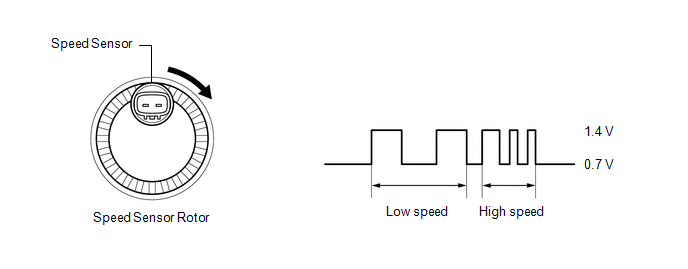
DESCRIPTION Each speed
sensor detects the wheel speed and sends the signals to the skid control
ECU (brake booster with master cylinder assembly). These signals are
used for ABS control. HINT: The
output voltage values shown below are for when the vehicle wire
harnesses are connected to the skid control ECU (brake booster with
master cylinder assembly) and the speed sensors.
 |
DTC No. | Detection Item |
INF Code | DTC Detection Condition |
Trouble Area | MIL |
Note | | C1415 |
Rear Speed Sensor RH Circuit Output |
524 543 |
- INF Code: 524
- An open in the sensor signal of a malfunctioning wheel occurs 255 times or more.
- INF Code: 543
- Either of the following is detected:
- At a vehicle speed of 20 km/h (12 mph) or more, noise occurs in the
sensor signals of a malfunctioning wheel 75 times or more within 5
seconds.
- At a vehicle speed of 10 km/h (6 mph) or more, noise occurs once per rotor rotation for 15 seconds or more.
|
- Skid control sensor wire RH (No. 1 parking brake wire assembly)
- Rear speed sensor RH (rear axle hub and bearing assembly RH)
- Speed sensor installed improperly
- Wire harness or connector
- Rear speed sensor rotor RH (rear axle hub and bearing assembly RH)
- Skid control ECU (brake booster with master cylinder assembly)
| Comes on |
- INF Code 524: SAE Code C0516 (Case 2)
- INF Code 543: SAE Code C0516 (Case 1)
- ABS DTC
| | C1416 |
Rear Speed Sensor LH Circuit Output |
534 544 |
- INF Code: 534
- An open in the sensor signal of a malfunctioning wheel occurs 255 times or more.
- INF Code: 544
- Either of the following is detected:
- At a vehicle speed of 20 km/h (12 mph) or more, noise occurs in the
sensor signals of a malfunctioning wheel 75 times or more within 5
seconds.
- At a vehicle speed of 10 km/h (6 mph) or more, noise occurs once per rotor rotation for 15 seconds or more.
|
- Skid control sensor wire LH (No. 2 parking brake wire assembly)
- Rear speed sensor LH (rear axle hub and bearing assembly LH)
- Speed sensor installed improperly
- Wire harness or connector
- Rear speed sensor rotor LH (rear axle hub and bearing assembly LH)
- Skid control ECU (brake booster with master cylinder assembly)
| Comes on |
- INF Code 534: SAE Code C0510 (Case 2)
- INF Code 544: SAE Code C0510 (Case 1)
- ABS DTC
| MONITOR DESCRIPTION
The
skid control ECU (brake booster with master cylinder assembly) monitors
the output value of the speed sensors. When the vehicle is being driven
and a sudden irregular change in acceleration due to iron particles
being attached to the speed sensor is detected repeatedly, or periodic
sudden changes in acceleration due to iron particles being attached to
the speed sensor rotor is detected, the skid control ECU (brake booster
with master cylinder assembly) judges that speed sensor noise is
occurring and illuminates the MIL and stores a DTC. Also,
when the vehicle is being driven and the output value of the speed
sensor is momentarily interrupted repeatedly, the skid control ECU
(brake booster with master cylinder assembly) judges that there is a
momentary interruption in the speed sensor circuit and illuminates the
MIL and stores a DTC. MONITOR STRATEGY |
Related DTCs | C0510 (Case 1): Speed sensor intermittent/erratic
C0510 (Case 2): Speed sensor intermittent/erratic C0516 (Case 1): Speed sensor intermittent/erratic
C0516 (Case 2): Speed sensor intermittent/erratic | |
Required Sensors/Components(Main) | Speed sensor
Speed sensor rotor | | Required Sensors/Components(Related) |
Speed sensor | | Frequency of Operation |
Continuous | | Duration |
-: C0510 (Case 1) and C0516 (Case 1) 255 times: C0510 (Case 2) and C0516 (Case 2) | |
MIL Operation | Immediately | |
Sequence of Operation | None | TYPICAL ENABLING CONDITIONS All |
Monitor runs whenever the following DTCs are not stored |
C0501, C0507, C050D, C0513 (Speed sensor range/performance) C0502, C0508, C050E, C0514 (Speed sensor circuit low)
C0503, C0509, C050F, C0515 (Speed sensor circuit high) C140B, C140C, C140D, C140E (2 wheel speed sensors malfunction)
C14E1, C14E4, C14E7, C14EA (Case 1) (Speed sensor voltage circuit low)
C14E1, C14E4, C14E7, C14EA (Case 2) (Speed sensor voltage circuit low) | C0510 and C0516 (Case 1) |
Speed
sensor fail (C0501, C0502, C0503, C0507, C0508, C0509, C050D, C050E,
C050F, C0513, C0514, C0515, C140B, C140C, C140D, C140E, C14E1, C14E4,
C14E7, C14EA) | Not detected | C0510 and C0516 (Case 2) |
All of the following conditions are met | - | |
Brake system voltage 1 (VM1) | Less than 16.44 V | |
Speed sensor pulse | No signal | |
Wheels are not locked | Met | |
Vehicle speed | 15 km/h (9 mph) or more | |
Speed
sensor fail (C0501, C0502, C0503, C0507, C0508, C0509, C050D, C050E,
C050F, C0513, C0514, C0515, C140B, C140C, C140D, C140E, C14E1, C14E4,
C14E7, C14EA) | Not detected | TYPICAL MALFUNCTION THRESHOLDS C0510 and C0516 (Case 1) |
Either of the following conditions is met | - | |
Speed sensor noise | Exist | |
Speed sensor a piece of metal rotor noise |
Exist | C0510 and C0516 (Case 2) |
Edge of speed sensor outage | Exist | COMPONENT OPERATING RANGE C0510 and C0516 (Case 1) |
Both of the following conditions are met |
- | | Speed
sensor fail (C0501, C0502, C0503, C0507, C0508, C0509, C050D, C050E,
C050F, C0513, C0514, C0515, C140B, C140C, C140D, C140E, C14E1, C14E4,
C14E7, C14EA) | Not detected | |
Speed sensor pass flag |
On | C0510 and C0516 (Case 2) |
All of the following conditions are met | - | |
Brake system voltage 1 (VM1) | Less than 16.44 V | |
Speed sensor pulse | No signal | |
Wheels are not locked | Met | |
Vehicle speed | 15 km/h (9 mph) or more | |
Speed
sensor fail (C0501, C0502, C0503, C0507, C0508, C0509, C050D, C050E,
C050F, C0513, C0514, C0515, C140B, C140C, C140D, C140E, C14E1, C14E4,
C14E7, C14EA) | Not detected | |
Speed sensor pass flag |
On | CONFIRMATION DRIVING PATTERN
- Connect the Techstream to the DLC3.
- Turn the power switch on (IG).
- Turn the Techstream on.
- Clear the DTCs (even if no DTCs are stored, perform the clear DTC procedure).
- Turn the power switch off.
- Turn the power switch on (READY).
- Turn the Techstream on.
- Drive the vehicle at a speed of 15 km/h (9 mph) or more for 15 seconds or more.
- Enter the following menus: Chassis / ABS/VSC/TRAC / Trouble Codes.
- Read the DTCs.
HINT:
- If a DTC is output, the system is malfunctioning.
- If a DTC is not output, perform the following procedure.
- If the DTCs are not output, perform a universal trip and check for permanent DTCs.
Click here 
HINT:
- If a permanent DTC is output, the system is malfunctioning.
- If no permanent DTCs are output, the system is normal.
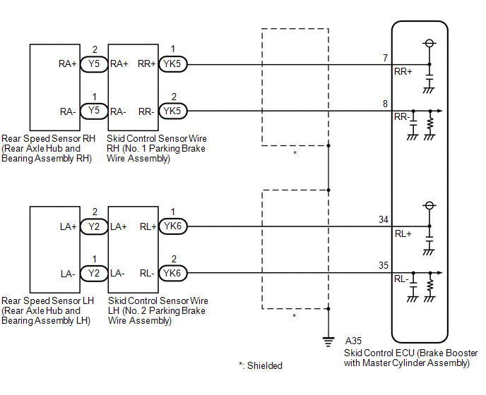
WIRING DIAGRAM
 CAUTION / NOTICE / HINT
NOTICE: After
replacing the skid control ECU (brake booster with master cylinder
assembly), perform linear solenoid valve offset learning, ABS holding
solenoid valve learning, yaw rate and acceleration sensor zero point
calibration and system information memorization after performing "Reset
Memory". Click here PROCEDURE
(a) Clear the DTCs. Click here
Chassis > ABS/VSC/TRAC > Clear DTCs
(b) Turn the power switch off. (c) Turn the power switch on (IG).
(d) Check if the same DTC is output. Click here
Chassis > ABS/VSC/TRAC > Trouble Codes
| Result |
Proceed to | | DTC C1415 is output. |
A | | DTC C1416 is output. |
B |
| B |
 | GO TO STEP 9 |
|
A |
 | |
| 2. |
READ VALUE USING TECHSTREAM (MOMENTARY INTERRUPTION) |
(a) Using the Techstream, check for any momentary interruptions in the wire harness and connector corresponding to a DTC.
Click here Chassis > ABS/VSC/TRAC > Data List
|
Tester Display | Measurement Item |
Range | Normal Condition |
Diagnostic Note | |
RR Speed Sensor Voltage Open |
Rear speed sensor RH voltage open detection |
Error or Normal | Error: Momentary interruption
Normal: Normal | - | Chassis > ABS/VSC/TRAC > Data List
|
Tester Display | | RR Speed Sensor Voltage Open |
(b) Check for any momentary interruptions in the wire harness and connectors.
OK: There are no momentary interruptions. NOTICE: Perform the above inspection before removing the sensor and connector.
| NG |
| GO TO STEP 5 |
|
OK | |
| |
| 3. |
READ VALUE USING TECHSTREAM (REAR SPEED SENSOR RH) |
(a) Select the Data List on the Techstream. Click here
Chassis > ABS/VSC/TRAC > Data List
|
Tester Display | Measurement Item |
Range | Normal Condition |
Diagnostic Note | |
RR Wheel Speed | Rear speed sensor RH |
Min.: 0 km/h (0 mph), Max.: 326.4 km/h (203 mph) |
Vehicle stopped: 0 km/h (0 mph) |
When driving at constant speed: No large fluctuations | Chassis > ABS/VSC/TRAC > Data List
|
Tester Display | | RR Wheel Speed |
(b) Check the rear speed sensor RH output value. OK: The output value changes in accordance with the vehicle speed.
| NG |
| GO TO STEP 5 |
|
OK | |
| |
(a) Clear the DTCs.
Click here Chassis > ABS/VSC/TRAC > Clear DTCs
(b) Turn the power switch off. (c) Turn the power switch on (READY).
(d) Perform a road test. (e) Check if the same DTC is output. Click here
Chassis > ABS/VSC/TRAC > Trouble Codes
| Result |
Proceed to | | DTC C1415 is not output. |
A | | DTC C1415 is output. |
B |
| A |
| USE SIMULATION METHOD TO CHECK |
| B |
| REPLACE BRAKE BOOSTER WITH MASTER CYLINDER ASSEMBLY |
| 5. |
CHECK REAR SPEED SENSOR RH INSTALLATION |
| (a) Turn the power switch off. |
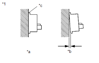 |
|
*1 | Rear Speed Sensor RH | |
*a | OK | |
*b | NG | |
*c | No Clearance | | |
(b) Check the rear speed sensor RH installation. OK: There is no clearance between the sensor and the rear axle hub.
HINT: Because
the rear axle hub and bearing assembly RH cannot be disassembled, if
the rear speed sensor RH needs replacement, replace the rear axle hub
and bearing assembly RH.
| NG | |
REPLACE REAR AXLE HUB AND BEARING ASSEMBLY RH |
|
OK | |
| |
| 6. |
INSPECT NO. 1 PARKING BRAKE WIRE ASSEMBLY |
| (a) Make sure that there is no looseness at the locking part and the connecting part of the connectors.
OK: The connector is securely connected. |
 |
|
*a | Front view of skid control sensor wire RH (No. 1 parking brake wire assembly) | |
*b | Front view of wire harness connector
(to Sensor Side Connector) | |
*c | Front view of wire harness connector
(to Vehicle Side Connector) | | |
(b) Disconnect the Y5 and YK5 skid control sensor wire RH (No. 1 parking brake wire assembly) connectors.
(c) Check both the connector case and the terminals for deformation and corrosion.
OK: No deformation or corrosion. (d) Measure the resistance according to the value(s) in the table below.
Standard Resistance: |
Tester Connection | Condition |
Specified Condition | |
Y5-2 (RA+) - YK5-1 (RR+) |
Always | Below 1 Ω | |
Y5-2 (RA+) or YK5-1 (RR+) - Body ground and other terminals |
Always | 10 kΩ or higher | |
Y5-1 (RA-) - YK5-2 (RR-) |
Always | Below 1 Ω | |
Y5-1 (RA-) or YK5-2 (RR-) - Body ground and other terminals |
Always | 10 kΩ or higher |
| NG |
| REPLACE NO. 1 PARKING BRAKE WIRE ASSEMBLY |
|
OK | |
| |
| 7. |
CHECK HARNESS AND CONNECTOR (BRAKE BOOSTER WITH MASTER CYLINDER ASSEMBLY - NO. 1 PARKING BRAKE WIRE ASSEMBLY) |
(a) Make sure that there is no looseness at the locking part and the connecting part of the connector.
OK: The connector is securely connected. (b) Disconnect the A35 skid control ECU (brake booster with master cylinder assembly) connector.
(c) Check both the connector case and the terminals for deformation and corrosion.
OK: No deformation or corrosion. (d) Measure the resistance according to the value(s) in the table below.
Standard Resistance: |
Tester Connection | Condition |
Specified Condition | |
A35-7 (RR+) - YK5-1 (RR+) |
Always | Below 1 Ω | |
A35-7 (RR+) or YK5-1 (RR+) - Body ground |
Always | 10 kΩ or higher | |
A35-8 (RR-) - YK5-2 (RR-) |
Always | Below 1 Ω | |
A35-8 (RR-) or YK5-2 (RR-) - Body ground |
Always | 10 kΩ or higher |
| NG |
| REPAIR OR REPLACE HARNESS OR CONNECTOR |
|
OK | |
| |
| 8. |
INSPECT BRAKE BOOSTER WITH MASTER CYLINDER ASSEMBLY (SENSOR OUTPUT) |
| (a) Reconnect the A35 skid control ECU (brake booster with master cylinder assembly) connector. |
 |
|
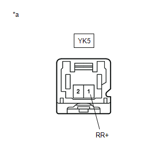
*a | Front view of wire harness connector
(to Skid Control Sensor Wire RH (No. 1 Parking Brake Wire Assembly)) | | |
(b) Turn the power switch on (IG). (c) Measure the voltage according to the value(s) in the table below.
Standard Voltage: |
Tester Connection | Condition |
Specified Condition | |
YK5-1 (RR+) - Body ground |
Power switch on (IG) |
8 to 14 V | NOTICE: Check the rear speed sensor RH signal after replacement.
Click here HINT: The rear speed sensor RH and rear speed sensor rotor RH are incorporated into the rear axle hub and bearing assembly RH.
If
the rear speed sensor RH and rear speed sensor rotor RH need to be
replaced, replace the rear axle hub and bearing assembly RH.
| OK |
| REPLACE REAR AXLE HUB AND BEARING ASSEMBLY RH |
| NG |
| REPLACE BRAKE BOOSTER WITH MASTER CYLINDER ASSEMBLY |
| 9. |
READ VALUE USING TECHSTREAM (MOMENTARY INTERRUPTION) |
(a) Using the Techstream, check for any momentary interruptions in the wire harness and connector corresponding to a DTC.
Click here Chassis > ABS/VSC/TRAC > Data List
|
Tester Display | Measurement Item |
Range | Normal Condition |
Diagnostic Note | |
RL Speed Sensor Voltage Open |
Rear speed sensor LH voltage open detection |
Error or Normal | Error: Momentary interruption
Normal: Normal | - | Chassis > ABS/VSC/TRAC > Data List
|
Tester Display | | RL Speed Sensor Voltage Open |
(b) Check for any momentary interruptions in the wire harness and connectors.
OK: There are no momentary interruptions. NOTICE: Perform the above inspection before removing the sensor and connector.
| NG |
| GO TO STEP 12 |
|
OK | |
| |
| 10. |
READ VALUE USING TECHSTREAM (REAR SPEED SENSOR LH) |
(a) Select the Data List on the Techstream. Click here
Chassis > ABS/VSC/TRAC > Data List
|
Tester Display | Measurement Item |
Range | Normal Condition |
Diagnostic Note | |
RL Wheel Speed | Rear speed sensor LH |
Min.: 0 km/h (0 mph), Max.: 326.4 km/h (203 mph) |
Vehicle stopped: 0 km/h (0 mph) |
When driving at constant speed: No large fluctuations | Chassis > ABS/VSC/TRAC > Data List
|
Tester Display | | RL Wheel Speed |
(b) Check the rear speed sensor LH output value. OK: The output value changes in accordance with the vehicle speed.
| NG |
| GO TO STEP 12 |
|
OK | |
| |
(a) Clear the DTCs.
Click here Chassis > ABS/VSC/TRAC > Clear DTCs
(b) Turn the power switch off. (c) Turn the power switch on (READY).
(d) Perform a road test. (e) Check if the same DTC is output. Click here
Chassis > ABS/VSC/TRAC > Trouble Codes
| Result |
Proceed to | | DTC C1416 is not output. |
A | | DTC C1416 is output. |
B |
| A |
| USE SIMULATION METHOD TO CHECK |
| B |
| REPLACE BRAKE BOOSTER WITH MASTER CYLINDER ASSEMBLY |
| 12. |
CHECK REAR SPEED SENSOR LH INSTALLATION |
| (a) Turn the power switch off. | |
|
|
*1 | Rear Speed Sensor LH | |
*a | OK | |
*b | NG | |
*c | No Clearance | | |
(b) Check the rear speed sensor LH installation. OK: There is no clearance between the sensor and the rear axle hub.
HINT: Because
the rear axle hub and bearing assembly LH cannot be disassembled, if
the rear speed sensor LH needs replacement, replace the rear axle hub
and bearing assembly LH.
| NG | |
REPLACE REAR AXLE HUB AND BEARING ASSEMBLY LH |
|
OK | |
| |
| 13. |
INSPECT NO. 2 PARKING BRAKE WIRE ASSEMBLY |
| (a) Make sure that there is no looseness at the locking part and the connecting part of the connectors.
OK: The connector is securely connected. |
 |
|
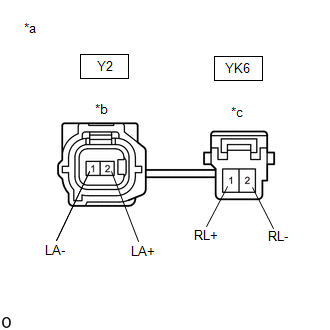
*a | Front view of skid control sensor wire LH (No. 2 parking brake wire assembly) | |
*b | Front view of wire harness connector
(to Sensor Side Connector) | |
*c | Front view of wire harness connector
(to Vehicle Side Connector) | | |
(b) Disconnect the Y2 and YK6 skid control sensor wire LH (No. 2 parking brake wire assembly) connectors.
(c) Check both the connector case and the terminals for deformation and corrosion.
OK: No deformation or corrosion. (d) Measure the resistance according to the value(s) in the table below.
Standard Resistance: |
Tester Connection | Condition |
Specified Condition | |
Y2-2 (LA+) - YK6-1 (RL+) |
Always | Below 1 Ω | |
Y2-2 (LA+) or YK6-1 (RL+) - Body ground and other terminals |
Always | 10 kΩ or higher | |
Y2-1 (LA-) - YK6-2 (RL-) |
Always | Below 1 Ω | |
Y2-1 (LA-) or YK6-2 (RL-) - Body ground and other terminals |
Always | 10 kΩ or higher |
| NG |
| REPLACE NO. 2 PARKING BRAKE WIRE ASSEMBLY |
|
OK | |
| |
| 14. |
CHECK HARNESS AND CONNECTOR (BRAKE BOOSTER WITH MASTER CYLINDER ASSEMBLY - NO. 2 PARKING BRAKE WIRE ASSEMBLY) |
(a) Make sure that there is no looseness at the locking part and the connecting part of the connector.
OK: The connector is securely connected. (b) Disconnect the A35 skid control ECU (brake booster with master cylinder assembly) connector.
(c) Check both the connector case and the terminals for deformation and corrosion.
OK: No deformation or corrosion. (d) Measure the resistance according to the value(s) in the table below.
Standard Resistance: |
Tester Connection | Condition |
Specified Condition | |
A35-34 (RL+) - YK6-1 (RL+) |
Always | Below 1 Ω | |
A35-34 (RL+) or YK6-1 (RL+) - Body ground |
Always | 10 kΩ or higher | |
A35-35 (RL-) - YK6-2 (RL-) |
Always | Below 1 Ω | |
A35-35 (RL-) or YK6-2 (RL-) - Body ground |
Always | 10 kΩ or higher |
| NG |
| REPAIR OR REPLACE HARNESS OR CONNECTOR |
|
OK | |
| |
| 15. |
INSPECT BRAKE BOOSTER WITH MASTER CYLINDER ASSEMBLY (SENSOR OUTPUT) |
| (a) Reconnect the A35 skid control ECU (brake booster with master cylinder assembly) connector. |
 |
|
*a | Front view of wire harness connector
(to Skid Control Sensor Wire LH (No. 2 Parking Brake Wire Assembly)) | | |
(b) Turn the power switch on (IG). (c) Measure the voltage according to the value(s) in the table below.
Standard Voltage: |
Tester Connection | Condition |
Specified Condition | |
YK6-1 (RL+) - Body ground |
Power switch on (IG) |
8 to 14 V | NOTICE: Check the rear speed sensor LH signal after replacement.
Click here HINT: The rear speed sensor LH and rear speed sensor rotor LH are incorporated into the rear axle hub and bearing assembly LH.
If
the rear speed sensor LH and rear speed sensor rotor LH need to be
replaced, replace the rear axle hub and bearing assembly LH.
| OK |
| REPLACE REAR AXLE HUB AND BEARING ASSEMBLY LH |
| NG |
| REPLACE BRAKE BOOSTER WITH MASTER CYLINDER ASSEMBLY | |


