DESCRIPTION When the power
switch is on (READY), the stop light switch assembly off and the vehicle
speed is 20 km/h (12 mph) or more, the skid control ECU (brake booster
with master cylinder assembly) performs a self-diagnosis of the ABS
motor relay circuit during the initial check of the actuator. |
DTC No. | Detection Item |
INF Code | DTC Detection Condition |
Trouble Area | MIL |
Note | | C1427 |
Malfunction in Motor |
1159 | The pump motor built into the brake actuator assembly is not operating correctly. |
- Wire harness or connector
- Pump motor or pump motor circuit built into the brake actuator assembly
| Comes on |
- INF Code 1159: SAE Code C1427
- Electronically controlled brake system DTC
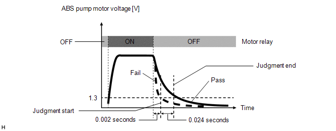
| MONITOR DESCRIPTION
The
skid control ECU (brake booster with master cylinder assembly) monitors
the voltage of the ABS motor. When the ABS motor is normal and the ABS
motor relay is turned off, the voltage of the ABS motor drops gradually
due to rotational inertia; however, if the ABS motor is not turning and
the ABS motor relay is turned off, the voltage of the ABS motor drops
immediately. If the voltage of the ABS motor drops considerably quickly
when the ABS motor relay is turned off, the skid control ECU (brake
booster with master cylinder assembly) judges that the ABS motor is not
operating and illuminates the MIL and stores this DTC.
 MONITOR STRATEGY |
Related DTCs | C1427: ABS pump motor stuck | |
Required Sensors/Components(Main) | Brake actuator assembly | |
Required Sensors/Components(Related) | Skid control ECU (brake booster with master cylinder assembly)
Brake actuator assembly | | Frequency of Operation |
Continuous | | Duration |
2 times | | MIL Operation | Immediately | |
Sequence of Operation | None | TYPICAL ENABLING CONDITIONS |
Monitor runs whenever the following DTCs are not stored |
None | | Both of the following conditions are met |
- | | Skid control ECU (brake booster with master cylinder assembly) state |
Initial check | | After command to ABS motor relay on to off detection, 0.002 seconds passes |
Met | TYPICAL MALFUNCTION THRESHOLDS |
ABS pump motor voltage | Less than 1.3 V for 0.022 seconds or more within 0.024 seconds | COMPONENT OPERATING RANGE |
All of the following conditions are met |
- | | Skid control ECU (brake booster with master cylinder assembly) state |
Initial check | |
After command to ABS motor relay on to off detection, 0.002 seconds passes |
Met | | ABS pump motor voltage |
Less than 1.3 V for less than 0.022 seconds within 0.024 seconds | CONFIRMATION DRIVING PATTERN
- Connect the Techstream to the DLC3.
- Turn the power switch on (IG).
- Turn the Techstream on.
- Clear the DTCs (even if no DTCs are stored, perform the clear DTC procedure).
- Turn the power switch off.
- Turn the power switch on (READY).
- Turn the Techstream on.
- Drive the vehicle at a speed of 20 km/h (12 mph) or more for 1 minute.
- Enter the following menus: Chassis / ABS/VSC/TRAC / Trouble Codes.
- Read the DTCs.
HINT:
- If a DTC is output, the system is malfunctioning.
- If a DTC is not output, perform the following procedure.
- If the DTCs are not output, perform a universal trip and check for permanent DTCs.
Click here 
HINT:
- If a permanent DTC is output, the system is malfunctioning.
- If no permanent DTCs are output, the system is normal.
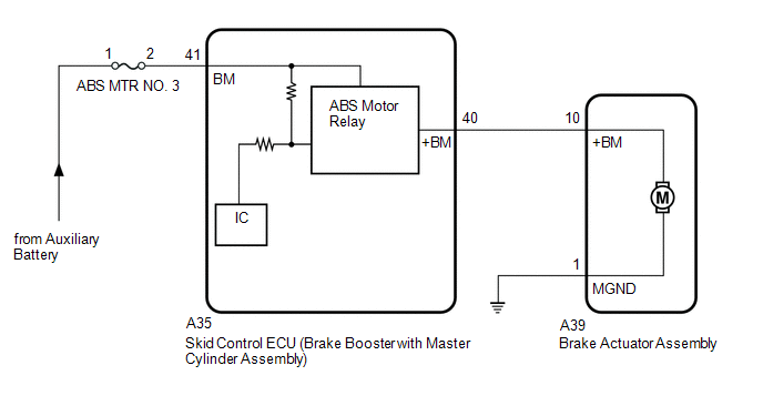
WIRING DIAGRAM
 CAUTION / NOTICE / HINT
NOTICE:
- After replacing the skid control ECU (brake booster with master cylinder
assembly) or brake actuator assembly, perform linear solenoid valve
offset learning, ABS holding solenoid valve learning, yaw rate and
acceleration sensor zero point calibration and system information
memorization after performing "Reset Memory".
Click here
- Inspect the fuses for circuits related to this system before performing the following procedure.
PROCEDURE |
1. | PERFORM ACTIVE TEST USING TECHSTREAM (ABS MOTOR RELAY) |
(a) Select the Active Test on the Techstream. Click here
Chassis > ABS/VSC/TRAC > Active Test
|
Tester Display | Measurement Item |
Control Range | Diagnostic Note | |
Motor Relay | ABS motor relay |
Relay ON/OFF | Operating sound of motor can be heard. | Chassis > ABS/VSC/TRAC > Active Test
|
Tester Display | | Motor Relay |
(b) Check the operating sound of the ABS motor relay when operating it with the Techstream.
| Result |
Proceed to | | The operating sound is heard. |
A | | The operating sound is not heard. |
B |
| B |
 | GO TO STEP 3 |
|
A |
 | |
(a) Clear the DTCs.
Click here Chassis > ABS/VSC/TRAC > Clear DTCs
(b) Turn the power switch off. (c) Turn the power switch on (READY).
(d) Perform a road test. (e) Check if the same DTC is output. Click here
Chassis > ABS/VSC/TRAC > Trouble Codes
| Result |
Proceed to | | DTC C1427 is not output. |
A | | DTC C1427 is output. |
B |
| A |
| USE SIMULATION METHOD TO CHECK |
| B |
| REPLACE BRAKE BOOSTER WITH MASTER CYLINDER ASSEMBLY |
| 3. |
CHECK HARNESS AND CONNECTOR (BRAKE BOOSTER WITH MASTER CYLINDER ASSEMBLY - BRAKE ACTUATOR ASSEMBLY) |
(a) Turn the power switch off. (b) Make sure that there is no looseness at the locking part and the connecting part of the connectors.
OK: The connector is securely connected. (c) Disconnect the A35 skid control ECU (brake booster with master cylinder assembly) connector.
(d) Disconnect the A39 brake actuator assembly connector. (e) Check both the connector case and the terminals for deformation and corrosion.
OK: No deformation or corrosion. (f) Measure the resistance according to the value(s) in the table below.
Standard Resistance: |
Tester Connection | Condition |
Specified Condition | |
A35-40 (+BM) - A39-10 (+BM) |
Always | Below 1 Ω | |
A35-40 (+BM) or A39-10 (+BM) - Body ground |
Always | 10 kΩ or higher |
| NG |
| REPAIR OR REPLACE HARNESS OR CONNECTOR |
|
OK | |
| |
| 4. |
CHECK HARNESS AND CONNECTOR (GND TERMINAL) |
| (a) Measure the resistance according to the value(s) in the table below.
Standard Resistance: |
Tester Connection | Condition |
Specified Condition | |
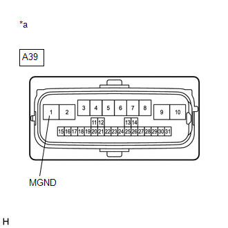
A39-1 (MGND) - Body ground |
Always | Below 1 Ω | |
 |
|
*a | Front view of wire harness connector
(to Brake Actuator Assembly) | | |
| NG |
| REPAIR OR REPLACE HARNESS OR CONNECTOR (GND CIRCUIT) |
|
OK | |
| |
(a) Reconnect the A35 skid control ECU (brake booster with master cylinder assembly) connector.
(b) Reconnect the A39 brake actuator assembly connector. (c) Clear the DTCs.
Click here Chassis > ABS/VSC/TRAC > Clear DTCs
(d) Turn the power switch off. (e) Turn the power switch on (READY).
(f) Perform a road test. (g) Check if the same DTC is output. Click here
Chassis > ABS/VSC/TRAC > Trouble Codes
| Result |
Proceed to | | DTC C1427 is not output. |
A | | DTC C1427 is output. |
B |
| A |
| USE SIMULATION METHOD TO CHECK |
| B |
| REPLACE BRAKE ACTUATOR ASSEMBLY | | 

