Toyota Avalon Service & Repair Manual: VSC OFF Switch Circuit

DESCRIPTION

The skid control ECU (brake booster with master cylinder assembly) is connected to the combination meter assembly via CAN communication.

Pressing the VSC OFF switch turns off TRAC operation, and pressing and holding this switch turns off TRAC and VSC operation. If TRAC and VSC operations are turned off, the "Traction Control Turned Off" will be displayed on the multi-information display and the VSC OFF indicator light will come on.

WIRING DIAGRAM

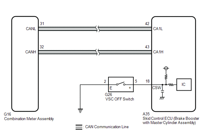
CAUTION / NOTICE / HINT

NOTICE:

After replacing the skid control ECU (brake booster with master cylinder assembly), perform linear solenoid valve offset learning, ABS holding solenoid valve learning, yaw rate and acceleration sensor zero point calibration and system information memorization after performing "Reset Memory".

Click here

PROCEDURE

1.

CHECK CAN COMMUNICATION SYSTEM

(a) Check if CAN communication system DTCs are output.

Click here

Result

Proceed to

DTCs are not output.

A

DTCs are output.

B

B

INSPECT CAN COMMUNICATION SYSTEM

A

2.

CHECK IF BRAKE BOOSTER WITH MASTER CYLINDER ASSEMBLY CONNECTOR IS SECURELY CONNECTED

(a) Check if the skid control ECU (brake booster with master cylinder assembly) connector is securely connected.

OK:

The connector is securely connected.

NG

CONNECT CONNECTOR TO BRAKE BOOSTER WITH MASTER CYLINDER ASSEMBLY CORRECTLY

OK

3.

READ VALUE USING TECHSTREAM (TRAC/VSC OFF MODE)

(a) Select the Data List on the Techstream.

Click here

Chassis > ABS/VSC/TRAC > Data List

Tester Display

Measurement Item

Range

Normal Condition

Diagnostic Note

TRAC/VSC Off Mode

TRAC/VSC off mode

Normal, TRC OFF, VSC Expert Mode or VSC OFF

Normal: Normal mode

TRC OFF: TRAC off mode

VSC Expert Mode: VSC expert mode

VSC OFF: VSC off mode

-

Chassis > ABS/VSC/TRAC > Data List

Tester Display

TRAC/VSC Off Mode

(b) Check the indicator light and mode condition on the Techstream changes according to VSC OFF switch operation.

Standard:

Switch Operation

Mode Condition Display

Multi-information Display (Traction Control Turned Off)

VSC OFF Indicator Light

Not pressed

Normal

Not displayed

Does not come on

Pressing the VSC OFF switch

TRC OFF

Displayed

Does not come on

Pressing and holding the VSC OFF switch

VSC OFF

Displayed

Comes on

Result

Proceed to

Indicator light and mode condition display do not change.

A

Mode condition display is normal, but indicator light does not change.

B

Indicator light and mode condition display are normal.

C

B

INSPECT METER / GAUGE SYSTEM

C

USE SIMULATION METHOD TO CHECK

A

4.

PERFORM ACTIVE TEST USING TECHSTREAM (MULTI-INFORMATION DISPLAY (TRACTION CONTROL TURNED OFF) AND VSC OFF INDICATOR LIGHT)

(a) Select the Active Test on the Techstream.

Click here

Chassis > ABS/VSC/TRAC > Active Test

Tester Display

Measurement Item

Control Range

Diagnostic Note

TRC(TRAC) OFF Indicator Light

Multi-information display (Traction Control Turned Off)

Display ON/OFF

Observe combination meter assembly

VSC OFF Indicator Light

VSC OFF indicator light

Indicator light ON/OFF

Observe combination meter assembly

Chassis > ABS/VSC/TRAC > Active Test

Tester Display

TRC(TRAC) OFF Indicator Light

Chassis > ABS/VSC/TRAC > Active Test

Tester Display

VSC OFF Indicator Light

(b) Check the multi-information display (Traction Control Turned Off) and VSC OFF indicator light on the combination meter assembly turn on or off in accordance with Techstream operation.

OK:

The multi-information display (Traction Control Turned Off) and VSC OFF indicator light turn on or off in accordance with Techstream operation.

NG

GO TO STEP 7

OK

5.

INSPECT VSC OFF SWITCH

(a) Turn the power switch off.

*a

Component without harness connected

(VSC OFF Switch)

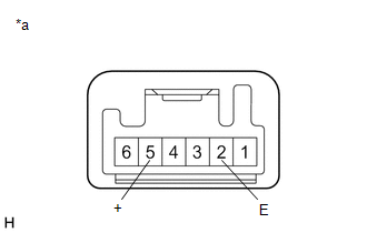
(b) Make sure that there is no looseness at the locking part and the connecting part of the connector.

OK:

The connector is securely connected.

(c) Disconnect the G26 VSC OFF switch connector.

(d) Check both the connector case and the terminals for deformation and corrosion.

OK:

No deformation or corrosion.

(e) Measure the resistance according to the value(s) in the table below.

Standard Resistance:

Tester Connection

Condition

Specified Condition

5 (+) - 2 (E)

Switch pushed

Below 1 Ω

5 (+) - 2 (E)

Switch not pushed

10 kΩ or higher

NG

REPLACE VSC OFF SWITCH

OK

6.

CHECK HARNESS AND CONNECTOR (BRAKE BOOSTER WITH MASTER CYLINDER ASSEMBLY - VSC OFF SWITCH)

(a) Make sure that there is no looseness at the locking part and the connecting part of the connector.

OK:

The connector is securely connected.

(b) Disconnect the A35 skid control ECU (brake booster with master cylinder assembly) connector.

(c) Check both the connector case and the terminals for deformation and corrosion.

OK:

No deformation or corrosion.

(d) Measure the resistance according to the value(s) in the table below.

Standard Resistance:

Tester Connection

Condition

Specified Condition

A35-18 (CSW) - G26-5 (+)

Always

Below 1 Ω

A35-18 (CSW) or G26-5 (+) - Body ground

Always

10 kΩ or higher

G26-2 (E) - Body ground

Always

Below 1 Ω

OK

REPLACE BRAKE BOOSTER WITH MASTER CYLINDER ASSEMBLY

NG

REPAIR OR REPLACE HARNESS OR CONNECTOR

7.

INSPECT COMBINATION METER ASSEMBLY

(a) Perform the Active Test of the combination meter assembly (meter CPU) using the Techstream.

Click here

Body Electrical > Combination Meter > Active Test

Tester Display

Multi Display All (White)

Body Electrical > Combination Meter > Active Test

Tester Display

VSC OFF Indicator

(b) Check the combination meter assembly.

OK:

The multi-information display and VSC OFF indicator light turn on or off in accordance with Techstream operation.

OK

REPLACE BRAKE BOOSTER WITH MASTER CYLINDER ASSEMBLY

NG

INSPECT METER / GAUGE SYSTEM

    VSC does not Operate or VSC does not Operate Correctly

    Front Speed Sensor

    See More:

    Toyota Avalon Service & Repair Manual > Panoramic View Monitor System(for Gasoline Model): Side Camera Current Malfunction (C1684)
    DESCRIPTION This DTC is stored if the parking assist ECU judges as a result of its self check that a synchronization problem is occurring in the image signal sent from the passenger side television camera assembly to the parking assist ECU. DTC No. Detection Item DTC Detection Condition Trouble Area ...

    Toyota Avalon Owners Manual

    Toyota Avalon Service & Repair Manual

    © 2024 Copyright www.tavalon.net
    0.0119