REMOVAL CAUTION / NOTICE / HINT The necessary procedures (adjustment, calibration, initialization, or registration) that must be performed after parts are removed, installed, or replaced during brake booster pump assembly removal/installation are shown below. Necessary Procedures After Parts Removed/Installed/Replaced
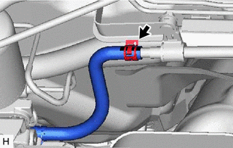
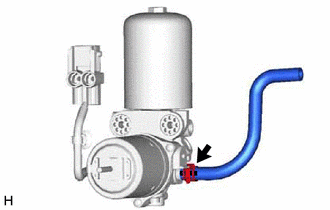
NOTICE: While the auxiliary battery is connected, even if the power switch is off, the brake control system activates when the brake pedal is depressed or any door courtesy switch turns on. Therefore, when servicing the brake system components, do not operate the brake pedal or open/close the doors while the auxiliary battery is connected. PROCEDURE 1. PRECAUTION NOTICE: After turning the power switch off, waiting time may be required before disconnecting the cable from the negative (-) auxiliary battery terminal. Therefore, make sure to read the disconnecting the cable from the negative (-) auxiliary battery terminal notices before proceeding with work. Click here 2. PERFORM ACCUMULATOR PRESSURE ZERO DOWN Click here 3. REMOVE COWL TOP VENTILATOR LOUVER SUB-ASSEMBLY Click here 4. REMOVE FRONT CENTER UPPER SUSPENSION BRACE SUB-ASSEMBLY Click here 5. REMOVE NO. 1 ENGINE COVER SUB-ASSEMBLY Click here 6. DRAIN BRAKE FLUID NOTICE: If brake fluid leaks onto any painted surface, immediately wash it off. 7. DISCONNECT NO. 2 BRAKE ACTUATOR HOSE
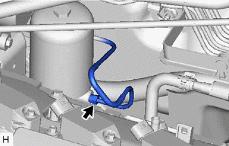
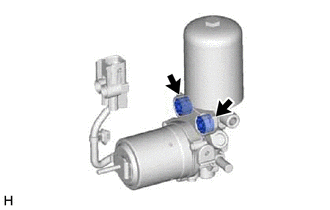
8. DISCONNECT ACCUMULATOR TO BRAKE MASTER CYLINDER TUBE
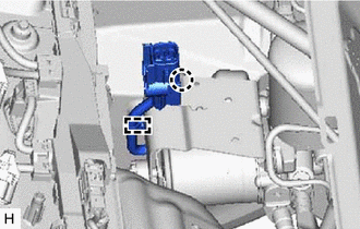
9. REMOVE BRAKE BOOSTER PUMP ASSEMBLY (a) Release the lock lever and disconnect the connector from the brake booster pump assembly as shown in the illustration. 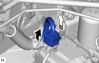
NOTICE: Be careful not to allow any brake fluid to enter the connector.
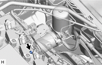
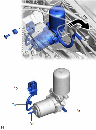
(d) Remove the brake booster pump assembly, brake booster pump bushing and brake actuator case collar from the brake actuator bracket assembly as shown in the illustration. NOTICE:
10. REMOVE NO. 2 BRAKE ACTUATOR HOSE
| ||||||||||||||||||||||||||||||||||||||||||||||||||||
Toyota Avalon (XX50) 2019-2022 Service & Repair Manual > Navigation System(for Gasoline Model): Reverse Signal Circuit between Radio Receiver Assembly and Navigation ECU
DESCRIPTION This circuit includes the navigation ECU and radio and display receiver assembly. WIRING DIAGRAM PROCEDURE 1. CHECK HARNESS AND CONNECTOR (RADIO AND DISPLAY RECEIVER ASSEMBLY - NAVIGATION ECU) (a) Disconnect the G1 radio and display receiver assembly connector. (b) Disconnect the G13 nav ...