REMOVAL CAUTION / NOTICE / HINT The necessary procedures (adjustment, calibration, initialization or registration) that must be performed after parts are removed and installed, or replaced during brake booster assembly removal/installation are shown below. Necessary Procedures After Parts Removed/Installed/Replaced
NOTICE: Make sure to release vacuum from the brake booster assembly before removing the brake master cylinder sub-assembly from the brake booster assembly. PROCEDURE 1. PRECAUTION NOTICE: After turning the engine switch off, waiting time may be required before disconnecting the cable from the negative (-) battery terminal. Therefore, make sure to read the disconnecting the cable from the negative (-) battery terminal notices before proceeding with work. Click here
2. REMOVE BRAKE MASTER CYLINDER SUB-ASSEMBLY Click here 3. REMOVE NO. 1 INSTRUMENT PANEL UNDER COVER SUB-ASSEMBLY Click here 4. REMOVE COWL TOP VENTILATOR LOUVER SUB-ASSEMBLY Click here 5. REMOVE FRONT CENTER UPPER SUSPENSION BRACE SUB-ASSEMBLY Click here 6. REMOVE AIR CLEANER ASSEMBLY WITH AIR CLEANER HOSE Click here 7. REMOVE BATTERY CLAMP SUB-ASSEMBLY
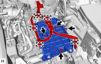
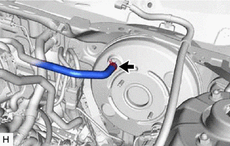
(b) Remove the 3 bolts, nut and battery clamp sub-assembly. 8. DISCONNECT UNION TO CHECK VALVE HOSE
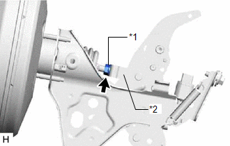
9. LOOSEN LOCK NUT
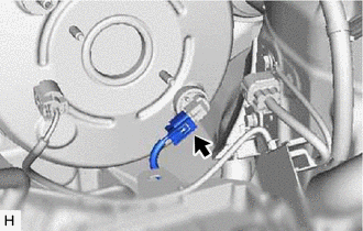
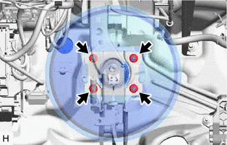
10. REMOVE PUSH ROD PIN Click here 11. REMOVE BRAKE BOOSTER ASSEMBLY
(c) Remove the brake master cylinder push rod clevis and lock nut from the brake booster assembly. (d) Remove the brake booster assembly from the vehicle body. NOTICE: Do not apply excessive force to the brake lines. 12. REMOVE BRAKE BOOSTER GASKET | ||||||||||||||||||||||||||||||||||||||||
Toyota Avalon (XX50) 2019-2022 Service & Repair Manual > Sfi System: Throttle/Pedal Position Sensor "A" Minimum Stop Performance (P210900)
DESCRIPTION The idle speed is controlled by the Electronic Throttle Control System (ETCS). The ETCS is comprised of a throttle actuator, which operates the throttle valve, and a throttle position sensor, which detects the opening amount of the throttle valve. The ECM controls the throttle actuator t ...