DESCRIPTION C13A1 is stored if the power supply relay in the parking brake ECU assembly has a short circuit.
C13A1
is stored if the power switch is off and a voltage of 2.5 V or higher
is applied to the IG terminal and an electric parking brake switch
assembly malfunction or wire harness malfunction between the switch and
ECU occurs. |
DTC No. | Detection Item |
DTC Detection Condition | Trouble Area |
Memory | Note | |
C13A1 | Short circuit in Power source circuit |
Both of following conditions are met:
- Electric parking brake switch (electric parking brake switch assembly) pulled to lock side with power switch off.
- Parking brake ECU (brake actuator assembly) power source relay shorted for approximately 60 seconds.
|
- Wire harness or connector
- Electric parking brake switch (electric parking brake switch assembly)
- Parking brake ECU (brake actuator assembly)
| DTC stored |
An electric parking brake system malfunction is displayed on the multi-information display. | WIRING DIAGRAM
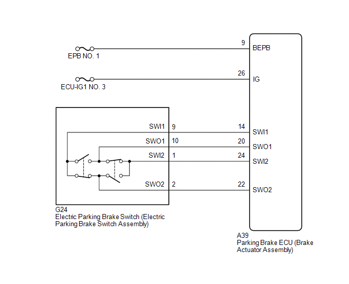 CAUTION / NOTICE / HINT
NOTICE:
- Inspect the fuses for circuits related to this system before performing the following procedure.
- The electric parking brake may still operate up to 20 seconds after the
power switch is turned off. Before disconnecting connectors or fuses,
turn the power switch off and wait 20 seconds or more.
- The parking brake indicator light blinks (red) when the power switch is
turned on (IG) after replacing the parking brake ECU (brake actuator
assembly). Operate the electric parking brake switch (electric parking
brake switch assembly) to turn off the parking brake indicator light
(red).
PROCEDURE |
1. | CHECK HARNESS AND CONNECTOR (BEPB CIRCUIT) |
|
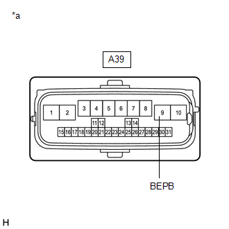
*a | Front view of wire harness connector (to Parking Brake ECU (Brake Actuator Assembly)) |
(a) Turn the power switch off. (b) Disconnect the A39 parking brake ECU (brake actuator assembly) connector.
(c) Measure the voltage according to the value(s) in the table below. Standard Voltage: |
Tester Connection | Condition |
Specified Condition | |
A39-9 (BEPB) - Body ground |
Power switch off | 11 to 14 V |
| NG |
 | REPAIR OR REPLACE HARNESS OR CONNECTOR |
|
OK |
 | |
| 2. |
CHECK HARNESS AND CONNECTOR (PARKING BRAKE ECU (BRAKE ACTUATOR ASSEMBLY) - IG POWER SOURCE CIRCUIT) |
|
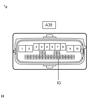
*a | Front view of wire harness connector
(to Parking Brake ECU (Brake Actuator Assembly)) |
(a) Turn the power switch off. (b) Disconnect the A39 parking brake ECU (brake actuator assembly) connector.
(c) Measure the voltage according to the value(s) in the table below. Standard Voltage: |
Tester Connection | Condition |
Specified Condition | |
A39-26 (IG) - Body ground |
Power switch off | Below 2.5 V |
| NG |
| REPAIR OR REPLACE HARNESS OR CONNECTOR |
|
OK | |
| |
| 3. |
INSPECT ELECTRIC PARKING BRAKE SWITCH (ELECTRIC PARKING BRAKE SWITCH ASSEMBLY) |
(a) Remove the electric parking brake switch (electric parking brake switch assembly).
Click here  (b) Inspect the electric parking brake switch (electric parking brake switch assembly).
Click here
| NG |
| REPLACE ELECTRIC PARKING BRAKE SWITCH (ELECTRIC PARKING BRAKE SWITCH ASSEMBLY) |
|
OK | |
| |
| 4. |
CHECK
HARNESS AND CONNECTOR (PARKING BRAKE ECU (BRAKE ACTUATOR ASSEMBLY) -
ELECTRIC PARKING BRAKE SWITCH (ELECTRIC PARKING BRAKE SWITCH ASSEMBLY)) |
|
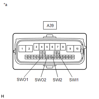
*a | Front view of wire harness connector
(to Parking Brake ECU (Brake Actuator Assembly)) |
(a) Disconnect the G24 electric parking brake switch (electric parking brake switch assembly) connector.
(b) Disconnect the A39 parking brake ECU (brake actuator assembly) connector.
(c) Measure the resistance according to the value(s) in the table below.
Standard Resistance: |
Tester Connection | Condition |
Specified Condition | |
A39-14 (SWI1) - Body ground |
Always | 10 kΩ or higher | |
A39-20 (SWO1) - Body ground |
Always | 10 kΩ or higher | |
A39-24 (SWI2) - Body ground |
Always | 10 kΩ or higher | |
A39-22 (SWO2) - Body ground |
Always | 10 kΩ or higher |
| OK |
| REPLACE PARKING BRAKE ECU (BRAKE ACTUATOR ASSEMBLY) |
| NG |
| REPAIR OR REPLACE HARNESS OR CONNECTOR | | 

