DESCRIPTION |
DTC No. | Detection Item |
DTC Detection Condition | Trouble Area |
Memory | Note | |
C13A7 | Actuator Malfunction |
Both of following conditions are met:
- Electric parking brake is operating
- One of following is detected: Motor lock, gear lock, motor spinning or repeated slipping
|
- Parking brake actuator assembly
- Rear brake
- Wire harness or connector
| DTC stored |
An electric parking brake system malfunction is displayed on the multi-information display. | DTC Detection Conditions | |
Vehicle Condition | |
Pattern 1 | Pattern 2 |
Pattern 3 | Pattern 4 | |
Diagnosis Condition | Electric parking brake is operating |
○ | ○ |
○ | ○ | |
Malfunction Status | Motor lock is detected |
○ | - |
- | - | |
Gear lock is detected |
- | ○ |
- | - | |
Motor spinning is detected |
- | - |
○ | - | |
Repeated slipping is detected |
- | - |
- | ○ | |
Detection Time | - |
- | - |
- | |
Number of Trips | 1 trip |
1 trip | 1 trip |
1 trip | HINT: DTC will be output when conditions for either of the patterns in the table above are met. WIRING DIAGRAM
Click here  CAUTION / NOTICE / HINT
NOTICE:
- This DTC may be stored when the system changes to pad replacement mode, but this is not a malfunction.
- This DTC may be stored when the parking brake is forcibly released, but this is not a malfunction.
- The electric parking brake may still operate up to 20 seconds after the
power switch is turned off. Before disconnecting connectors or fuses,
turn the power switch off and wait 20 seconds or more.
- The parking brake indicator light blinks (red) when the power switch is
turned on (IG) after replacing the parking brake ECU (brake actuator
assembly). Operate the electric parking brake switch (electric parking
brake switch assembly) to turn off the parking brake indicator light
(red).
PROCEDURE (a) Check for DTCs.
Click here Chassis > Electric Parking Brake > Trouble Codes
| Result |
Proceed to | | Only DTC C13A7 is output |
A | | DTCs other than C13A7 are output |
B |
| B |
 | GO TO DIAGNOSTIC TROUBLE CODE CHART |
|
A |
 | |
| 2. |
READ VALUE USING TECHSTREAM (PERMISSION OF RH INTERLOCKING PKB LOCK / PERMISSION OF LH INTERLOCKING PKB LOCK) |
(a) Turn the power switch off. (b) Connect the Techstream to the DLC3.
(c) Turn the power switch on (IG). (d) Turn the Techstream on. (e) Enter the following menus: Chassis / Electric Parking Brake / Data List.
(f) Read the Data List according to the display on the Techstream. Chassis > Electric Parking Brake > Data List
|
Tester Display | Measurement Item |
Range | Normal Condition |
Diagnostic Note | |
Permission of RH Interlocking PKB Lock |
Parking brake actuator assembly RH parking brake lock control permission status |
OK or NG | OK |
- | | Permission of LH Interlocking PKB Lock |
Parking brake actuator assembly RH parking brake lock control permission status |
OK or NG | OK |
- | Chassis > Electric Parking Brake > Data List
|
Tester Display | | Permission of RH Interlocking PKB Lock | |
Permission of LH Interlocking PKB Lock |
|
NEXT | |
| |
| 3. |
INSPECT PARKING BRAKE WIRE ASSEMBLY |
|
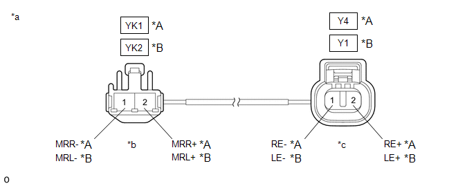
*A | RH |
*B | LH | |
*a | Front view of Parking Brake Wire Assembly |
*b | (to wire harness connector) | |
*c | (to Parking Brake Actuator Assembly) |
- | - |
(a) Turn the engine switch off. (b) Make sure that there is no looseness at the locking part and the connecting part of the connectors.
OK: The connector is securely connected. (c) Remove the parking brake wire assembly.
(d) Check both the connector case and the terminals for deformation and corrosion.
OK: No deformation or corrosion. (e) Inspect the parking brake wire assembly.
Standard Resistance: RH |
Tester Connection | Condition |
Specified Condition | |
YK1-1 (MRR-) - Y4-1 (RE-) |
Always | Below 1 Ω | |
YK1-1 (MRR-) or Y4-1 (RE-) - Body ground and other terminals |
Always | 10 kΩ or higher | |
YK1-2 (MRR+) - Y4-2 (RE+) |
Always | Below 1 Ω | |
YK1-2 (MRR+) or Y4-2 (RE+) - Body ground and other terminals |
Always | 10 kΩ or higher | LH |
Tester Connection | Condition |
Specified Condition | |
YK2-1 (MRL-) - Y1-1 (LE-) |
Always | Below 1 Ω | |
YK2-1 (MRL-) or Y1-1 (LE-) - Body ground and other terminals |
Always | 10 kΩ or higher | |
YK2-2 (MRL+) - Y1-2 (LE+) |
Always | Below 1 Ω | |
YK2-2 (MRL+) or Y1-2 (LE+) - Body ground and other terminals |
Always | 10 kΩ or higher |
| NG |
| REPLACE PARKING BRAKE WIRE ASSEMBLY |
|
OK | |
| |
| 4. |
CHECK HARNESS AND CONNECTOR (PARKING BRAKE ECU (BRAKE ACTUATOR ASSEMBLY) - PARKING BRAKE ACTUATOR ASSEMBLY) |
(a) Turn the power switch off. (b) Make sure the parking brake wire assembly is securely installed.
(c) Disconnect the A39 parking brake ECU (brake actuator assembly) connector.
(d) Disconnect the Y4 or Y1 parking brake actuator assembly connector.
(e) Measure the resistance according to the value(s) in the table below.
Standard Resistance: RH |
Tester Connection | Condition |
Specified Condition | |
A39-4 (MRR+) - Y4-2 (RE+) |
Always | Below 1 Ω | |
A39-3 (MRR-) - Y4-1 (RE-) |
Always | Below 1 Ω | |
A39-4 (MRR+) or Y4-2 (RE+) - Body ground |
Always | 10 kΩ or higher | |
A39-3 (MRR-) or Y4-1 (RE-) - Body ground |
Always | 10 kΩ or higher | LH |
Tester Connection | Condition |
Specified Condition | |
A39-7 (MRL+) - Y1-2 (LE+) |
Always | Below 1 Ω | |
A39-8 (MRL-) - Y1-1 (LE-) |
Always | Below 1 Ω | |
A39-7 (MRL+) or Y1-2 (LE+) - Body ground |
Always | 10 kΩ or higher | |
A39-8 (MRL-) or Y1-1 (LE-) - Body ground |
Always | 10 kΩ or higher |
| NG |
| REPAIR OR REPLACE HARNESS OR CONNECTOR |
|
OK | |
| |
| 5. |
INSPECT REAR BRAKE AND PARKING BRAKE ACTUATOR ASSEMBLY |
(a) Enter rear brake pad replacement mode. Click here
(b) Turn the power switch off. (c) Check that the rotating parts are not seized or the actuator is not spinning freely.
(1)
Check that the parking brake actuator assembly is installed properly to
the rear brake caliper and that it is not spinning freely. For the parking brake actuator assembly removal procedure: Click here
(2) Check that there is no damage to the rotating parts from the parking brake actuator assembly to the rear brake caliper.
(3) Inspect the parking brake actuator assembly and check that it operates correctly.
Click here (4) Check that the rear brake caliper threaded part rotates and that the rear disc brake piston moves outward.
HINT: For the check procedures, refer to the parking brake forced release method when not using the Techstream.
Click here HINT: Return to normal mode after work is complete.
Click here
| OK |
| REPLACE PARKING BRAKE ACTUATOR ASSEMBLY |
| NG |
| REPAIR OR REPLACE NECESSARY PARTS | | 

