INSTALLATION CAUTION / NOTICE / HINT for HV Model:
HINT:
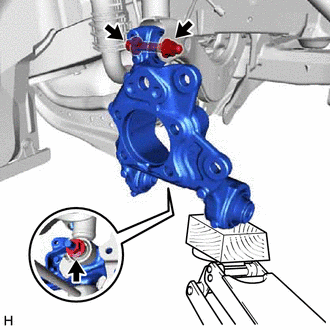
PROCEDURE 1. TEMPORARILY INSTALL REAR AXLE CARRIER SUB-ASSEMBLY (a) Temporarily install the rear axle carrier sub-assembly to the rear shock absorber assembly with the nut and plate washer. NOTICE: Hold the rear axle carrier pin while rotating the nut.
(c) Install the rear trailing arm assembly to the rear axle carrier sub-assembly with the 2 bolts. Torque: 135 N·m {1377 kgf·cm, 100 ft·lbf} 2. INSTALL REAR FLEXIBLE HOSE BRACKET (a) Install the rear flexible hose bracket to the rear axle carrier sub-assembly with the bolt. Torque: 29 N·m {296 kgf·cm, 21 ft·lbf} 3. TEMPORARILY INSTALL REAR NO. 1 SUSPENSION ARM ASSEMBLY Click here 4. INSTALL REAR LOWER COIL SPRING INSULATOR Click here 5. INSTALL REAR COIL SPRING Click here 6. STABILIZE SUSPENSION Click here 7. INSTALL REAR UPPER CONTROL ARM ASSEMBLY (a) Install the rear upper control arm assembly to the rear axle carrier sub-assembly with the bolt. Torque: 73 N·m {744 kgf·cm, 54 ft·lbf} NOTICE: Because the nut has its own stopper, do not turn the nut. Tighten the bolt with the nut secured. 8. INSTALL REAR NO. 1 SUSPENSION ARM ASSEMBLY Click here
9. INSTALL REAR NO. 2 SUSPENSION ARM ASSEMBLY (a) Install the rear No. 2 suspension arm assembly (rear axle carrier sub-assembly side) with the bolt. Click here 10. INSTALL REAR SHOCK ABSORBER ASSEMBLY Click here 11. INSTALL REAR STABILIZER LINK ASSEMBLY Click here 12. INSTALL REAR AXLE HUB AND BEARING ASSEMBLY Click here 13. INSTALL REAR DISC Click here 14. INSTALL REAR DISC BRAKE CALIPER ASSEMBLY Click here 15. INSTALL REAR FLEXIBLE HOSE (a) Install the rear flexible hose to the rear flexible hose bracket with the bolt. Torque: 29 N·m {296 kgf·cm, 21 ft·lbf} 16. INSTALL NO. 2 PARKING BRAKE WIRE ASSEMBLY (w/o AVS)
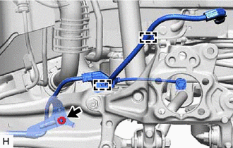
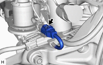
(b) Engage the 2 clamps. (c) Connect the No. 2 parking brake wire assembly connector to the parking brake actuator assembly. (d) Connect the No. 2 parking brake wire assembly connector to the rear axle hub and bearing assembly. 17. INSTALL NO. 2 PARKING BRAKE WIRE ASSEMBLY (w/ AVS)
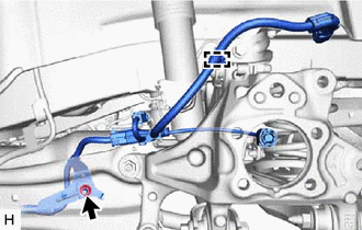
(b) Engage the clamp.
(d) Install the nut. Torque: 8.5 N·m {87 kgf·cm, 75 in·lbf} (e) Engage the clamp and install the No. 2 parking brake wire assembly to the wire harness bracket.
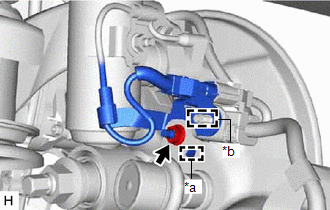
(g) Connect the No. 2 parking brake wire assembly connector to the parking brake actuator assembly. (h) Connect the No. 2 parking brake wire assembly connector to the rear axle hub and bearing assembly. 18. INSTALL NO. 1 FLOOR UNDER COVER (for Gasoline Model) (a) for RH Side: Click here 19. INSTALL NO. 2 FLOOR UNDER COVER (for Gasoline Model) (a) for LH Side: Click here 20. INSTALL REAR WHEEL Click here 21. INSTALL REAR NO. 2 SUSPENSION ARM ASSEMBLY (a) Install the rear No. 2 suspension arm assembly (rear suspension member sub-assembly side) with the nut. Click here 22. CONNECT CABLE TO NEGATIVE AUXILIARY BATTERY TERMINAL (for HV Model) (a) Connect the reservoir level switch connector. (b) Connect the cable to the negative (-) auxiliary battery terminal. Click here (c) Turn the power switch on (READY). (d) Depress the brake pedal and release it. (e) Clear the DTCs. Click here 23. INSPECT AND ADJUST REAR WHEEL ALIGNMENT Click here 24. CHECK FOR SPEED SENSOR SIGNAL for HV Model: Click here for Gasoline Model: Click here
25. PERFORM INITIALIZATION for Gasoline Model:
|
Toyota Avalon (XX50) 2019-2022 Service & Repair Manual > Can Communication System(for Hv Model): Data List / Active Test
DATA LIST / ACTIVE TEST NOTICE: In the table below, the values listed under "Normal Condition" are reference values. Do not depend solely on these reference values when deciding whether a part is faulty or not. HINT: Using the Techstream to read the Data List allows the values or states of switches, ...