REMOVAL CAUTION / NOTICE / HINT
The
necessary procedures (adjustment, calibration, initialization, or
registration) that must be performed after parts are removed and
installed, or replaced during rear axle carrier sub-assembly
removal/installation are shown below. Necessary Procedures After Parts Removed/Installed/Replaced (for Gasoline Model:) |
Replaced Part or Performed Procedure |
Necessary Procedure | Effect/Inoperative Function when Necessary Procedure not Performed |
Link | | Rear wheel alignment adjustment |
Perform system variant learning and acceleration sensor zero point calibration. |
- VSC disabled or malfunctioning
- DTCs are output
- Slip indicator light illuminated
- ABS warning light illuminated
|
 | |
Suspension, tires, etc. (The vehicle height changes because of suspension or tire replacement.) |
- Measure ultrasonic sensor detection angle
- Ultrasonic sensor detection angle registration
|
- Intelligent Clearance Sonar System
- Intuitive Parking Assist System
|
| |
Rear television camera assembly optical axis adjustment (Back camera position setting) |
Parking Assist Monitor System |
for Initialization
for Calibration |
- Parking assist ECU initialization
- Adjust steering angle
- Television camera assembly optical axis adjustment (Back camera position setting)
| Panoramic View Monitor System |
for Initialization
for Calibration | Necessary Procedures After Parts Removed/Installed/Replaced (for HV Model:) |
Replaced Part or Performed Procedure |
Necessary Procedure | Effect/Inoperative Function when Necessary Procedure not Performed |
Link | |
*: When performing learning using the Techstream.
Click here | |
Auxiliary battery terminal is disconnected/reconnected |
Perform steering sensor zero point calibration |
Lane Departure Alert System (w/ Steering Control) |
| |
Pre-collision System | |
Intelligent Clearance Sonar System* | |
Lighting System (for HV Model with Cornering Light) | |
Memorize steering angle neutral point |
Parking Assist Monitor System |
| |
Panoramic View Monitor System |
| |
Rear wheel alignment adjustment |
- Clear zero point calibration data.
- Perform yaw rate and acceleration sensor zero point calibration.
|
- DTCs are stored
- ABS warning light illuminates
- Brake warning light / yellow (minor malfunction) illuminates
- Slip indicator light illuminates
- VSC disabled or malfunctions
|
| |
Suspension, tires, etc. (The vehicle height changes because of suspension or tire replacement.) |
- Measure ultrasonic sensor detection angle
- Ultrasonic sensor detection angle registration
|
- Intelligent Clearance Sonar System
- Intuitive Parking Assist System
|
| |
Rear television camera assembly optical axis adjustment (Back camera position setting) |
Parking Assist Monitor System |
for Initialization
for Calibration |
- Parking assist ECU initialization
- Adjust steering angle
- Television camera assembly optical axis adjustment (Back camera position setting)
| Panoramic View Monitor System |
for Initialization
for Calibration | for HV Model:
- When removing or installing the rear disc brake caliper assembly,
pushing back the disc brake piston may cause a large clearance between
the brake pads and brake disc. When the brake pedal is depressed with a
large clearance between the brake pads and the brake disc, DTC C1214
related to abnormal brake fluid pressure may be stored. Make sure to
clear any DTCs after performing this procedure.
- While the auxiliary battery is connected, even if the power switch is
off, the brake control system activates when the brake pedal is
depressed or any door courtesy switch turns on. Therefore, when
servicing the brake system components, do not operate the brake pedal or
open/close the doors while the auxiliary battery is connected.
HINT:
- Use the same procedure for the RH side and LH side.
- The following procedure is for the LH side.
PROCEDURE 1. PRECAUTION (for HV Model) NOTICE:
After
turning the power switch off, waiting time may be required before
disconnecting the cable from the negative (-) auxiliary battery
terminal. Therefore, make sure to read the disconnecting the cable from
the negative (-) auxiliary battery terminal notices before proceeding
with work. Click here 2. DISABLE BRAKE CONTROL (for HV Model)
Click here 3. REMOVE REAR WHEEL
Click here 4. REMOVE NO. 2 FLOOR UNDER COVER (for Gasoline Model)
(a) for LH Side: Click here 5. REMOVE NO. 1 FLOOR UNDER COVER (for Gasoline Model)
(a) for RH Side: Click here 6. SEPARATE NO. 2 PARKING BRAKE WIRE ASSEMBLY (w/o AVS)
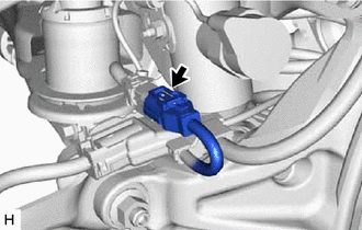
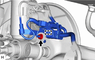
| (a) Disconnect the No. 2 parking brake wire assembly connector from the parking brake actuator assembly.
NOTICE:
- Remove any dirt or foreign matter on and around the No. 2 parking brake wire assembly connector before performing this step.
- Do not allow water, oil or dirt to enter the No. 2 parking brake wire assembly connector.
| |
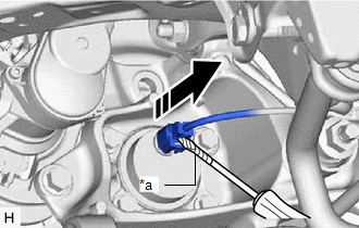
| (b)
Using a screwdriver with its tip wrapped with protective tape,
disconnect the No. 2 parking brake wire assembly connector from the rear
axle hub and bearing assembly. NOTICE: Be careful not to damage the rear axle hub and bearing assembly or connector cover. |
|
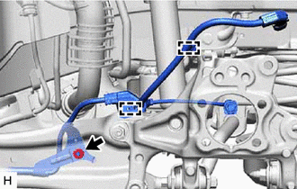
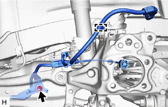
| (c)
Remove the nut, disengage the 2 clamps and separate the No. 2 parking
brake wire assembly from the rear flexible hose bracket and rear
trailing arm assembly. | |
7. SEPARATE NO. 2 PARKING BRAKE WIRE ASSEMBLY (w/ AVS)
| (a) Disconnect the No. 2 parking brake wire assembly connector from the parking brake actuator assembly.
NOTICE:
- Remove any dirt or foreign matter on and around the No. 2 parking brake wire assembly connector before performing this step.
- Do not allow water, oil or dirt to enter the No. 2 parking brake wire assembly connector.
| |
| (b)
Using a screwdriver with its tip wrapped with protective tape,
disconnect the No. 2 parking brake wire assembly connector from the rear
axle hub and bearing assembly. NOTICE: Be careful not to damage the rear axle hub and bearing assembly or connector cover. |
|
| (c) Disconnect the connector. | |
| (d) Remove the nut and disengage the clamp. | |
| (e)
Remove the nut, disengage the clamp and separate the No. 2 parking
brake wire assembly from the rear flexible hose bracket and rear
trailing arm assembly. | |
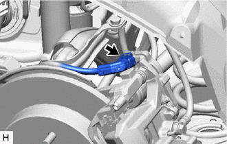
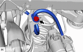
8. SEPARATE REAR FLEXIBLE HOSE
| (a) Remove the bolt and separate the rear flexible hose from the rear flexible hose bracket. |
|
9. SEPARATE REAR DISC BRAKE CALIPER ASSEMBLY Click here
10. REMOVE REAR DISC Click here
11. REMOVE REAR AXLE HUB AND BEARING ASSEMBLY
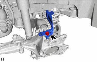
Click here 12. REMOVE REAR FLEXIBLE HOSE BRACKET
| (a) Remove the bolt and rear flexible hose bracket from the rear axle carrier sub-assembly. |
|
13. REMOVE REAR STABILIZER LINK ASSEMBLY Click here
14. REMOVE REAR COIL SPRING Click here
15. REMOVE REAR LOWER COIL SPRING INSULATOR
Click here 16. REMOVE REAR NO. 1 SUSPENSION ARM ASSEMBLY
Click here 17. REMOVE REAR AXLE CARRIER SUB-ASSEMBLY
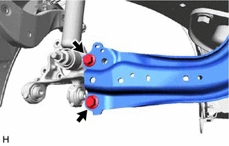
| (a) Loosen the 2 bolts of the rear trailing arm assembly. |
|
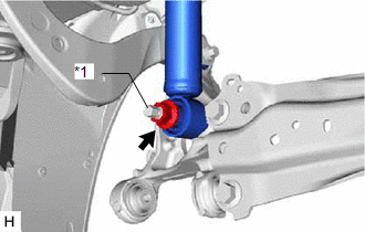
| (b) Loosen the nut of the rear shock absorber assembly. NOTICE:
Hold the rear axle carrier pin while rotating the nut. | |
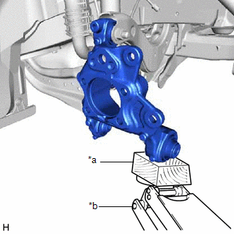
| (c) Using a jack and wooden block, support the rear axle carrier sub-assembly.
NOTICE:
- When jacking up the rear axle carrier sub-assembly, be sure to jack it up slowly.
- Make sure to perform this operation with the vehicle kept as low as possible.
| |
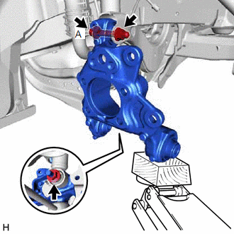
| (d) Loosen the bolt (A). NOTICE: Because the nut has its own stopper, do not turn the nut. Loosen the bolt with the nut secured. |
|
(e) Remove the 2 bolts and separate the rear trailing arm assembly from the rear axle carrier sub-assembly.
(f) Remove the nut and plate washer, and separate the rear shock absorber assembly from the rear axle carrier sub-assembly.
NOTICE: Hold the rear axle carrier pin while rotating the nut. (g) Remove the bolt (A), nut and rear axle carrier sub-assembly from the rear upper control arm assembly.
NOTICE: Because the nut has its own stopper, do not turn the nut. Loosen the bolt with the nut secured. |