INSTALLATION CAUTION / NOTICE / HINT HINT:
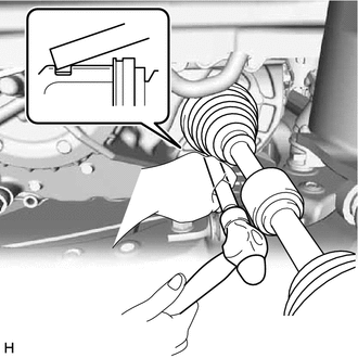
PROCEDURE 1. INSTALL FRONT DRIVE SHAFT HOLE SNAP RING (a) Install a new front drive shaft hole snap ring. NOTICE: Face the end gap of the front drive shaft hole snap ring downward. 2. INSTALL FRONT DRIVE SHAFT ASSEMBLY LH (a) Coat the snap ring of the front drive inboard joint assembly LH with MP grease. (b) Coat the splines of the front drive inboard joint assembly LH with ATF WS. (c) Coat the lip of the front drive shaft oil seal LH with MP grease and Toyota genuine oil seal side lip grease as shown in the illustration. 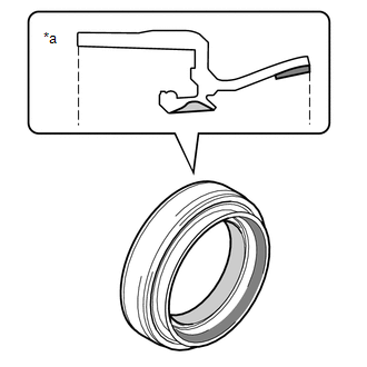
HINT: Apply a light coat of MP grease and Toyota genuine oil seal side lip grease to the entire circumference of the front drive shaft oil seal LH.
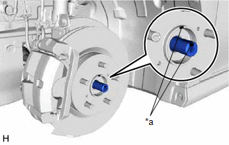
(e) Apply 0.1 to 0.3 g (0.00353 to 0.0105 oz) of Toyota Body Grease W to each of the 4 areas shown in the illustration. 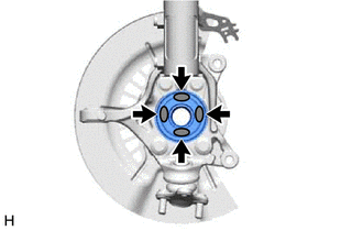
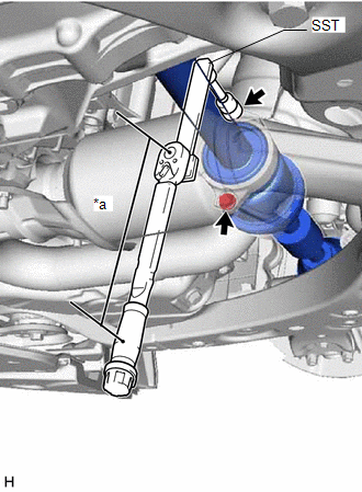
3. INSTALL FRONT DRIVE SHAFT ASSEMBLY RH (a) Coat the splines of the front drive inboard joint assembly RH with ATF WS. (b) Coat the lip of the front drive shaft oil seal RH with MP grease and Toyota genuine oil seal side lip grease as shown in the illustration. HINT: Apply a light coat of Toyota genuine oil seal side lip grease to the entire circumference of the front drive shaft oil seal RH. 
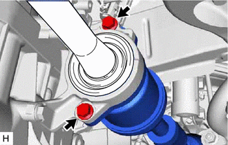
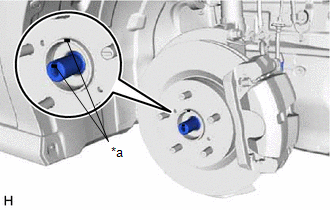
(c) Align the inboard joint splines, and securely insert the front drive shaft assembly RH. NOTICE:
(d) for Gasoline Model:
(e) for HV Model:
(f) Apply 0.1 to 0.3 g (0.00353 to 0.0105 oz) of Toyota Body Grease W to each of the 4 areas shown in the illustration. 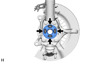
4. CONNECT FRONT LOWER NO. 1 SUSPENSION ARM SUB-ASSEMBLY Click here
5. INSTALL FRONT STABILIZER LINK ASSEMBLY Click here 6. CONNECT TIE ROD ASSEMBLY (for Gasoline Model) Click here 7. CONNECT TIE ROD ASSEMBLY (for HV Model) Click here 8. INSTALL FRONT SPEED SENSOR (w/o AVS) Click here 9. INSTALL FRONT SPEED SENSOR (w/ AVS) Click here 10. INSTALL FRONT AXLE SHAFT NUT (a) Clean the threaded parts on the front drive shaft assembly and a new front axle shaft nut using non-residue solvent. NOTICE:
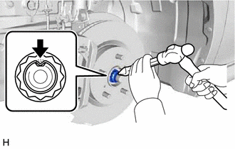
(c) Using a chisel and hammer, stake the front axle shaft nut. 11. ADD AUTOMATIC TRANSAXLE FLUID (for Gasoline Model) Click here 12. ADD HYBRID TRANSAXLE FLUID (for HV Model) Click here 13. INSPECT HYBRID TRANSAXLE FLUID (for HV Model) Click here 14. INSPECT FOR HYBRID TRANSAXLE FLUID LEAK (for HV Model) 15. INSTALL FRONT WHEELS Click here 16. INSPECT AND ADJUST FRONT WHEEL ALIGNMENT Click here
17. INSTALL FRONT FENDER APRON SEAL LH (for Gasoline Model) Click here 18. INSTALL FRONT FENDER APRON SEAL RH (for Gasoline Model) Click here 19. INSTALL REAR ENGINE UNDER COVER RH (for Gasoline Model) Click here 20. INSTALL REAR ENGINE UNDER COVER LH (for Gasoline Model) Click here 21. INSTALL NO. 1 ENGINE UNDER COVER (for Gasoline Model) Click here 22. INSTALL FRONT WHEEL OPENING EXTENSION PAD LH (for Gasoline Model) Click here 23. INSTALL FRONT WHEEL OPENING EXTENSION PAD RH (for Gasoline Model) Click here 24. INSTALL FRONT FENDER APRON SEAL LH (for HV Model) Click here 25. INSTALL FRONT FENDER APRON SEAL RH (for HV Model) Click here 26. INSTALL NO. 2 ENGINE UNDER COVER ASSEMBLY (for HV Model) Click here 27. INSTALL NO. 1 ENGINE UNDER COVER (for HV Model) Click here 28. INSTALL FRONT WHEEL OPENING EXTENSION PAD LH (for HV Model) Click here 29. INSTALL FRONT WHEEL OPENING EXTENSION PAD RH (for HV Model) Click here 30. CHECK FOR SPEED SENSOR SIGNAL (for Gasoline Model) Click here 31. CHECK FOR SPEED SENSOR SIGNAL (for HV Model) Click here |
Toyota Avalon (XX50) 2019-2022 Service & Repair Manual > Rear Seat Assembly: Removal
REMOVAL CAUTION / NOTICE / HINT The necessary procedures (adjustment, calibration, initialization or registration) that must be performed after parts are removed and installed, or replaced during rear seat assembly removal/installation are shown below. Necessary Procedure After Parts Removed/Install ...