INSTALLATION PROCEDURE 1. INSTALL TRANSMISSION WIRE
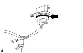
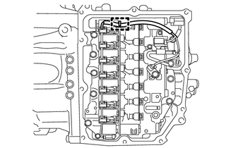
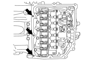
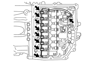
(b) Install the transmission wire to the automatic transaxle case sub-assembly with the bolt. Torque: 5.4 N·m {55 kgf·cm, 48 in·lbf} (c) Connect the transmission revolution sensor (NT) connector and transmission revolution sensor (NC) connector. (d) Install the temperature sensor to the transmission valve body assembly with the bolt and temperature sensor clamp. Torque: 10.8 N·m {110 kgf·cm, 8 ft·lbf} NOTICE: To prevent it from being pinched between the transmission valve body assembly and the transmission case side cover, pass the transmission revolution sensor (NC) wire under the transmission wire (temperature sensor wire) as shown in the illustration. 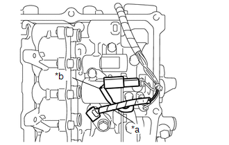
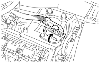
(e) Connect the 9 solenoid valve connectors. 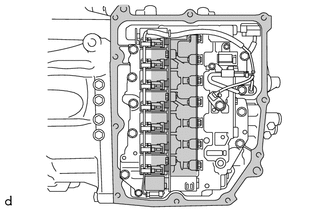
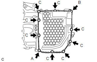
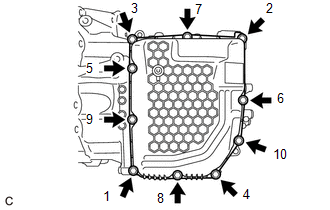
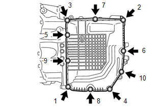
2. INSTALL TRANSMISSION CASE SIDE COVER (for TMC Made) HINT: TMC Made and TMMWV Made components can be identified by the location where the serial number is stamped. 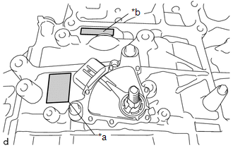
(a) Clean the transmission case side cover installation surface of the automatic transaxle case sub-assembly. 
NOTICE: Completely remove any oil or grease from the contact surfaces of the automatic transaxle case sub-assembly.
(c) Temporarily install the 8 bolts (C).
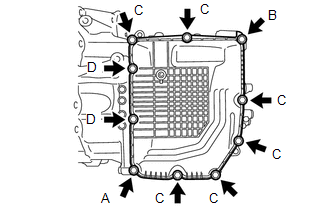
3. INSTALL TRANSMISSION CASE SIDE COVER (for TMMWV Made) HINT: TMC Made and TMMWV Made components can be identified by the location where the serial number is stamped.
(a) Clean the transmission case side cover installation surface of the automatic transaxle case sub-assembly.
NOTICE: Completely remove any oil or grease from the contact surfaces of the automatic transaxle case sub-assembly.
(e) Temporarily install the 6 bolts (C) and 2 bolts (D). NOTICE: Bolt (D) is an adhesive-coated bolt.
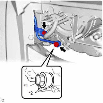
4. INSTALL OIL COOLER UNION SUB-ASSEMBLY
(b) Temporarily install the oil cooler union sub-assembly bracket portion to the automatic transaxle case sub-assembly with the bolt. (c) Fully tighten the oil cooler union bolt. Torque: 22.6 N·m {230 kgf·cm, 17 ft·lbf} (d) Fully tighten the bolt. Torque: 12 N·m {122 kgf·cm, 9 ft·lbf} 5. INSTALL FRONT SUSPENSION MEMBER DYNAMIC DAMPER Click here 6. INSTALL FRONT ENGINE MOUNTING INSULATOR Click here 7. ADJUST AUTOMATIC TRANSAXLE FLUID Click here 8. INSTALL FRONT FENDER APRON SEAL LH Click here 9. INSTALL REAR ENGINE UNDER COVER LH Click here 10. INSTALL NO. 1 ENGINE UNDER COVER Click here 11. INSTALL FRONT WHEEL OPENING EXTENSION PAD LH Click here 12. INSTALL FRONT WHEEL OPENING EXTENSION PAD RH Click here 13. INSTALL FRONT WHEEL LH Click here |
Toyota Avalon (XX50) 2019-2022 Service & Repair Manual > Water Pump: Removal
REMOVAL CAUTION / NOTICE / HINT The necessary procedures (adjustment, calibration, initialization or registration) that must be performed after parts are removed and installed, or replaced during engine water pump assembly removal/installation are shown below. Necessary Procedure After Parts Removed ...