DESCRIPTION ACIS (Acoustic Control Induction System) controls the opening and closing the intake air control valve sub-assembly built into the intake air surge tank assembly to increase the intake efficiency according to the engine load. When the engine speed is between 0 and 4300 rpm and the throttle valve opening angle is 30° or more, the ECM activates the No. 1 vacuum switching valve (for intake air control valve sub-assembly) which then applies vacuum from the vacuum pump assembly to the diaphragm actuator sub-assembly and closes the intake air control valve sub-assembly. When the engine speed and/or throttle valve opening angle are not as specified above, the ECM deactivates the No. 1 vacuum switching valve (for intake air control valve sub-assembly), causing the intake air control valve sub-assembly to open. 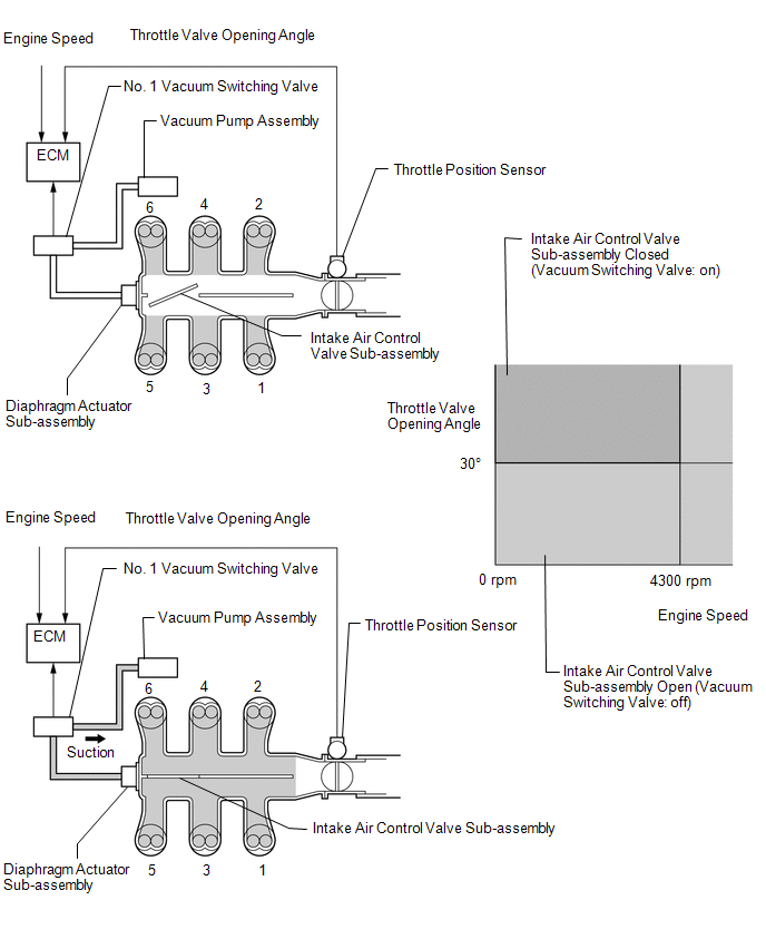 WIRING DIAGRAM 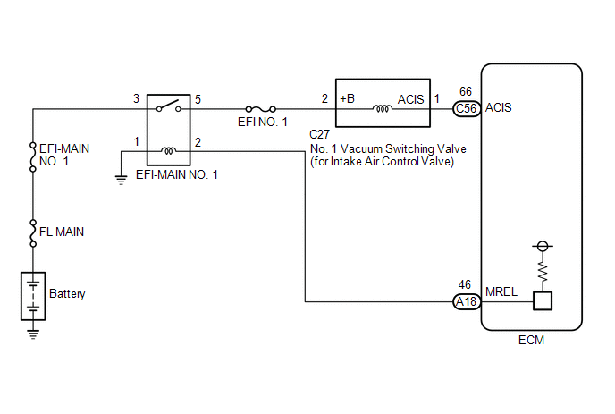 CAUTION / NOTICE / HINT NOTICE: Inspect the fuses for circuits related to this system before performing the following procedure. PROCEDURE
(a) Connect the Techstream to the DLC3. (b) Start the engine. (c) Turn the Techstream on. (d) Enter the following menus: Powertrain / Engine / Active Test / Activate the VSV for Intake Control. Powertrain > Engine > Active Test
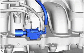
(e) According to the display on the Techstream, perform the Active Test to operate the No. 1 vacuum switching valve (for intake air control valve sub-assembly) and check for the operating sound of the intake air control valve sub-assembly in the intake air surge tank assembly. OK: Operating sounds can be heard.
(a) Inspect the intake air surge tank assembly (intake air control valve sub-assembly). Click here
(a) Check the vacuum hose sub-assembly (No. 1 vacuum switching valve (for intake air control valve sub-assembly) - intake air surge tank assembly) for looseness, disconnection and blockage. OK: No looseness, disconnection or blockage.
(b) Start the engine. (c) Using your finger, confirm that the hose has suction.
(a) Inspect the No. 1 vacuum switching valve (for intake air control valve sub-assembly). Click here
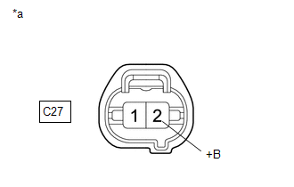
(b) Turn the engine switch on (IG). (c) Measure the voltage according to the value(s) in the table below. Standard Voltage:
(a) Disconnect the No. 1 vacuum switching valve (for intake air control valve sub-assembly) connector. (b) Disconnect the ECM connector. (c) Measure the resistance according to the value(s) in the table below. Standard Resistance:
(a) Remove the EFI-MAIN NO. 1 relay from the No. 1 engine room relay block and No. 1 junction block assembly. (b) Disconnect the No. 1 vacuum switching valve (for intake air control valve sub-assembly) connector. (c) Measure the resistance according to the value(s) in the table below. Standard Resistance:
(a) Inspect the vacuum pump assembly. Click here
|
Toyota Avalon (XX50) 2019-2022 Service & Repair Manual > Lighting System(for Gasoline Model With Cornering Light): Left Headlight ECU Variation Error (B2456)
DESCRIPTION This DTC is stored if the headlight ECU sub-assembly LH for another destination is installed. DTC No. Detection Item DTC Detection Condition Trouble Area DTC Output from B2456 Left Headlight ECU Variation Error The engine switch is on (IG). Vehicle specification information received via ...