Toyota Avalon (XX50) 2019-2022 Service & Repair Manual: Actuator Supply Voltage "A" Circuit Short to Ground or Open (P065714)

Toyota Avalon (XX50) 2019-2022 Service & Repair Manual / Engine / 2gr-fks Engine Control / Sfi System / Actuator Supply Voltage "A" Circuit Short to Ground or Open (P065714)

DESCRIPTION

The electronic throttle control system has a dedicated power supply circuit. The voltage (+BM) is monitored and when it is low (less than 4 V), the ECM determines that there is a malfunction in the electronic throttle control system and cuts off the current to the throttle actuator.

When the voltage becomes unstable, the electronic throttle control system itself becomes unstable. For this reason, when the voltage is low, the current to the throttle actuator is cut. If repairs are made and the system returns to normal, turn the engine switch off. If a malfunction is not detected the ECM allows current to flow to the throttle actuator so that it can operate.

HINT:

The electronic throttle control system does not use a throttle cable.

DTC No.

Detection Item

DTC Detection Condition

Trouble Area

MIL

Memory

Note

P065714

Actuator Supply Voltage "A" Circuit Short to Ground or Open

An open or short is detected in the electronic throttle control system power source (+BM) circuit (1 trip detection logic).

  • Open or short in electronic throttle control system power source circuit
  • Battery
  • Battery terminals
  • ETCS fuse
  • ECM

Comes on

DTC stored

SAE Code: P0658

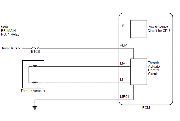
MONITOR DESCRIPTION

The ECM monitors the battery supply voltage applied to the throttle actuator.

When the power supply voltage (+BM) is less than 4 V for 0.8 seconds or more, the ECM interprets this as an open or ground in the power supply circuit, then illuminates the MIL and stores this DTC.

MONITOR STRATEGY

Related DTCs

P0658: Electronic throttle actuator power supply voltage circuit range check (low voltage)

Required Sensors/Components (Main)

Throttle actuator

Throttle valve (throttle body with motor assembly)

ETCS fuse

Required Sensors/Components (Related)

-

Frequency of Operation

Continuous

Duration

0.8 seconds

MIL Operation

Immediate

Sequence of Operation

None

TYPICAL ENABLING CONDITIONS

Monitor runs whenever the following DTCs are not stored

None

Both of the following conditions are met

-

Command to electronic throttle actuator power

On

Battery voltage

8 V or higher

TYPICAL MALFUNCTION THRESHOLDS

Throttle actuator power supply voltage (+BM)

Less than 4 V

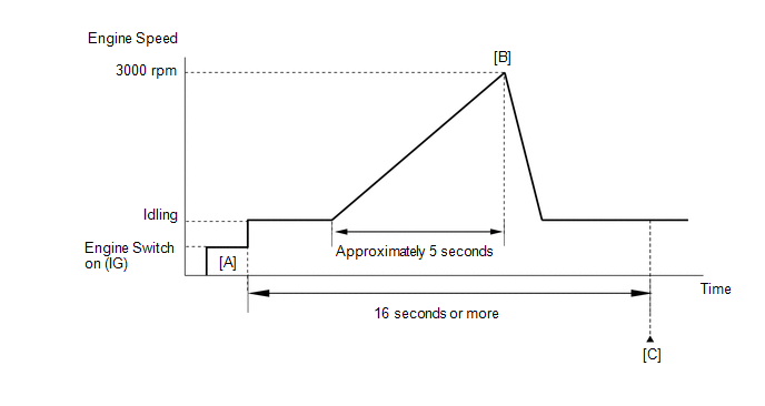
CONFIRMATION DRIVING PATTERN

HINT:

  • After repair has been completed, clear the DTC and then check that the vehicle has returned to normal by performing the following All Readiness check procedure.

    Click here

  • When clearing the permanent DTCs, refer to the "CLEAR PERMANENT DTC" procedure.

    Click here

  1. Connect the Techstream to the DLC3.
  2. Turn the engine switch on (IG).
  3. Turn the Techstream on.
  4. Clear the DTCs (even if no DTCs are stored, perform the clear DTC procedure).
  5. Turn the engine switch off and wait for at least 30 seconds.
  6. Turn the engine switch on (IG) [A].
  7. Turn the Techstream on.
  8. Start the engine.
  9. Slowly depress the accelerator pedal, raise the engine speed to approximately 3000 rpm over approximately 5 seconds, and then idle the engine [B].
  10. Check that 16 seconds or more have elapsed since the engine was started.
  11. Enter the following menus: Powertrain / Engine / Trouble Codes [C].
  12. Read the pending DTCs.

    HINT:

    • If a pending DTC is output, the system is malfunctioning.
    • If a pending DTC is not output, perform the following procedure.
  13. Enter the following menus: Powertrain / Engine / Utility / All Readiness.
  14. Input the DTC: P065714.
  15. Check the DTC judgment result.

    Techstream Display

    Description

    NORMAL

    • DTC judgment completed
    • System normal

    ABNORMAL

    • DTC judgment completed
    • System abnormal

    INCOMPLETE

    • DTC judgment not completed
    • Perform driving pattern after confirming DTC enabling conditions

    HINT:

    • If the judgment result shows NORMAL, the system is normal.
    • If the judgment result shows ABNORMAL, the system has a malfunction.
    • If the judgment result is INCOMPLETE, perform steps [B] through [C] again.
    • [A] to [C]: Normal judgment procedure.

      The normal judgment procedure is used to complete DTC judgment and also used when clearing permanent DTCs.

    • When clearing the permanent DTCs, do not disconnect the cable from the battery terminal or attempt to clear the DTCs during this procedure, as doing so will clear the universal trip and normal judgment histories.

FAIL-SAFE

When any of these DTCs or other DTCs relating to Electronic Throttle Control System (ETCS) malfunctions are stored, the ECM enters fail-safe mode. During fail-safe mode, the ECM cuts the current to the throttle actuator, and the throttle valve is returned to a 7° throttle valve opening angle by the return spring. The ECM then adjusts the engine output by controlling the fuel injection (intermittent fuel-cut) and ignition timing, in accordance with the accelerator pedal opening angle, to allow the vehicle to be driven at a low speed. If the accelerator pedal is depressed firmly and gently, the vehicle can be driven slowly.

Fail-safe mode continues until a pass condition is detected, and the engine switch is then turned off.

WIRING DIAGRAM

Refer to DTC P210014.

Click here

CAUTION / NOTICE / HINT

NOTICE:

Inspect the fuses for circuits related to this system before performing the following procedure.

HINT:

Read freeze frame data using the Techstream. The ECM records vehicle and driving condition information as freeze frame data the moment a DTC is stored. When troubleshooting, freeze frame data can help determine if the vehicle was moving or stationary, if the engine was warmed up or not, if the air fuel ratio was lean or rich, and other data from the time the malfunction occurred.

PROCEDURE

1.

READ VALUE USING TECHSTREAM (+BM VOLTAGE)

(a) Connect the Techstream to the DLC3.

(b) Turn the engine switch on (IG).

(c) Turn the Techstream on.

(d) Enter the following menus: Powertrain / Engine / Data List / +BM Voltage.

Powertrain > Engine > Data List

Tester Display

+BM Voltage

(e) According to the display on the Techstream, read the Data List.

Standard Voltage:

11 to 14 V

OK

CHECK FOR INTERMITTENT PROBLEMS

NG

2.

CHECK HARNESS AND CONNECTOR (BATTERY - ECM, BODY GROUND)

(a) Disconnect the ECM connector.

(b) Measure the voltage according to the value(s) in the table below.

Standard Voltage:

Tester Connection

Condition

Specified Condition

A18-8 (+BM) - Body ground

Always

11 to 14 V

(c) Measure the resistance according to the value(s) in the table below.

Standard Resistance:

Tester Connection

Condition

Specified Condition

C56-49 (ME01) - Body ground

Always

Below 1 Ω

C56-53 (E1) - Body ground

Always

Below 1 Ω

OK

REPLACE ECM

NG

REPAIR OR REPLACE HARNESS OR CONNECTOR

    VIN Not Programmed (P063051)

    Brake Switch "B" Circuit Short to Battery (P070312)

    See More:

    Toyota Avalon (XX50) 2019-2022 Service & Repair Manual > Navigation System(for Gasoline Model): Lost Communication with Meter (B1324,B1325)
    DESCRIPTION These DTCs are stored when communication between the radio and display receiver assembly and combination meter assembly or headup display (meter mirror sub-assembly) is not possible. DTC No. Detection Item DTC Detection Condition Trouble Area B1324 Lost Communication with Meter CAN recep ...

    Toyota Avalon (XX50) 2019-2022 Owners Manual

    Toyota Avalon (XX50) 2019-2022 Service & Repair Manual

    © 2024 Copyright www.tavalon.net
    0.0139