DESCRIPTION Refer to DTC P219519. Click here
HINT: Although the DTC titles say O2 sensor, these DTCs relate to the air fuel ratio sensor.
MONITOR DESCRIPTION These DTCs are output when there is an open or short in the air fuel ratio sensor circuit, or if the air fuel ratio sensor output drops. To detect these problems, the voltage of the air fuel ratio sensor is monitored when turning the engine switch on (IG), and the admittance (admittance is an electrical term that indicates the ease of flow of current) is checked while driving. If the voltage of the air fuel ratio sensor is between 0.5 V and 4.5 V, it is considered normal. If the voltage is out of the specified range, or the admittance is less than the standard value, the ECM determines that there is a malfunction in the air fuel ratio sensor. If the same malfunction is detected in the next driving cycle, the ECM will illuminate the MIL and store a DTC. MONITOR STRATEGY
TYPICAL ENABLING CONDITIONS P2237, P2238, P2240 and P2241
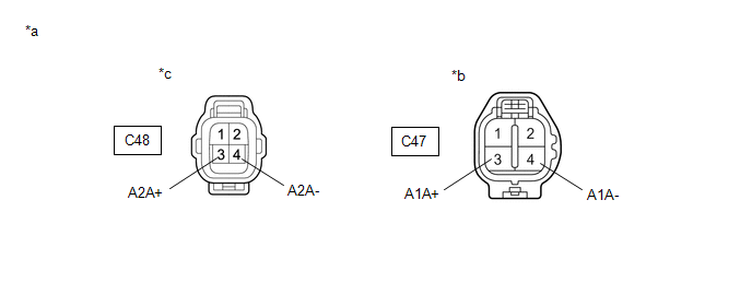
TYPICAL MALFUNCTION THRESHOLDS P2237 and P2240: Open Circuit Between A1A+ and A1A- / A2A+ and A2A-
CONFIRMATION DRIVING PATTERN HINT:
WIRING DIAGRAM Refer to DTC P219519. Click here
CAUTION / NOTICE / HINT NOTICE: Inspect the fuses for circuits related to this system before performing the following procedure. HINT:
PROCEDURE
HINT: Make sure that the connector is properly connected. If it is not, securely connect it and check for DTCs again. (a) Disconnect the air fuel ratio sensor connector. (b) Turn the engine switch on (IG). (c) Measure the voltage according to the value(s) in the table below. Standard Voltage:
HINT: Perform "Inspection After Repair" after replacing the air fuel ratio sensor. Click here
(a) Disconnect the air fuel ratio sensor connector. (b) Disconnect the ECM connector. (c) Measure the resistance according to the value(s) in the table below. Standard Resistance:
|
Toyota Avalon (XX50) 2019-2022 Service & Repair Manual > Trip Switch: Installation
INSTALLATION PROCEDURE 1. INSTALL TRIP SWITCH (a) Engage the 4 claws as shown in the illustration to install the trip switch. Install in this Direction 2. INSTALL NO. 1 INSTRUMENT PANEL SUB-ASSEMBLY Click here 3. CONNECT HOOD LOCK CONTROL LEVER SUB-ASSEMBLY Click here 4. INSTALL NO. 1 INSTRUMENT PAN ...


