INSTALLATION CAUTION / NOTICE / HINT CAUTION:
PROCEDURE 1. INSTALL ENGINE MOUNTING INSULATOR LH HINT: Perform this procedure only when replacement of the engine mounting insulator LH is necessary. Click here 2. INSTALL ENGINE MOUNTING BRACKET SUB-ASSEMBLY LH HINT: Perform this procedure only when replacement of the engine mounting bracket sub-assembly LH is necessary.
3. INSTALL ENGINE MOUNTING SPACER HINT: Perform this procedure only when replacement of the engine mounting spacer is necessary.
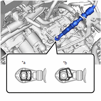
4. INSTALL ENGINE MOUNTING INSULATOR SUB-ASSEMBLY RH HINT: Perform this procedure only when replacement of the engine mounting insulator sub-assembly RH is necessary.
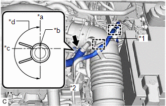
(b) Engage the clamp. (c) Install the bracket to the engine mounting insulator sub-assembly RH with the bolt. Torque: 8.0 N·m {82 kgf·cm, 71 in·lbf}
(e) Engage the clamp. 5. INSTALL ENGINE HANGERS Click here
6. REMOVE ENGINE ASSEMBLY FROM ENGINE STAND (a) Remove the engine assembly from the engine stand. 7. INSTALL CRANKSHAFT POSITION SENSOR PLATE NO.1 Click here 8. INSTALL DRIVE PLATE AND RING GEAR SUB-ASSEMBLY Click here 9. INSTALL AUTOMATIC TRANSAXLE ASSEMBLY Click here 10. INSTALL FRONT ENGINE MOUNTING BRACKET Click here 11. INSTALL REAR ENGINE MOUNTING INSULATOR HINT: Perform this procedure only when replacement of the rear engine mounting insulator is necessary. Click here 12. INSTALL FRONT ENGINE MOUNTING INSULATOR HINT: Perform this procedure only when replacement of the front engine mounting insulator is necessary. (a) Install the front engine mounting insulator to the front frame assembly with the 3 nuts. Torque: 72 N·m {734 kgf·cm, 53 ft·lbf} 13. INSTALL FRONT FRAME ASSEMBLY (a) Install the rear engine mounting insulator to the front frame assembly with the 4 nuts. Torque: 72 N·m {734 kgf·cm, 53 ft·lbf} (b) Install the front engine mounting insulator to the front engine mounting bracket with the bolt. Torque: 72 N·m {734 kgf·cm, 53 ft·lbf} 14. REMOVE ENGINE HANGERS Click here 15. INSTALL ENGINE WIRE (a) Connect all connectors and clamps, and install the engine wire to the engine assembly with transaxle. 16. CONNECT WATER BY-PASS HOSE ASSEMBLY Click here
17. CONNECT NO. 1 WATER BY-PASS HOSE Click here 18. INSTALL BREATHER PLUG HOSE Click here 19. INSTALL STARTER ASSEMBLY Click here 20. CONNECT VACUUM HOSE Click here 21. INSTALL ENGINE ASSEMBLY WITH TRANSAXLE HINT: Perform Inspection After Repair after replacing the engine assembly. Click here (a) Using height adjustment attachments and plate lift attachments to keep the engine assembly with transaxle and front frame assembly level, set an engine lifter underneath the engine assembly with transaxle and front frame assembly. NOTICE:
(b) Operate the engine lifter and install the engine assembly with transaxle to the vehicle. CAUTION: Do not raise the engine assembly with transaxle more than necessary. If the engine is raised excessively, the vehicle may also be lifted up. NOTICE:
(c) Install the front bumper extension sub-assembly RH and front bumper extension sub-assembly LH to the front frame assembly and vehicle body with the 8 bolts. 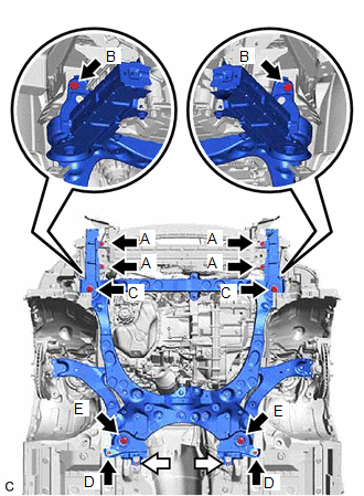
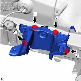
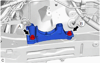
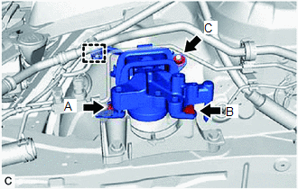
Torque: Bolt (A) : 9.0 N·m {92 kgf·cm, 80 in·lbf} Bolt (B) : 12.5 N·m {127 kgf·cm, 9 ft·lbf} Bolt (C) : 135 N·m {1377 kgf·cm, 100 ft·lbf} (d) Install the front suspension member bracket sub-assembly RH and front suspension member bracket sub-assembly LH to the front frame assembly and vehicle body with the 4 bolts and 2 nuts. Torque: Bolt (D) : 17.5 N·m {178 kgf·cm, 13 ft·lbf} Bolt (E) : 135 N·m {1377 kgf·cm, 100 ft·lbf} Nut : 17.5 N·m {178 kgf·cm, 13 ft·lbf} (e) Install the engine mounting insulator LH to the engine mounting bracket sub-assembly LH with the bolt and nut. Torque: 42 N·m {428 kgf·cm, 31 ft·lbf} (f) Install the engine mounting insulator sub-assembly RH to the front No. 1 engine mounting bracket LH with the 3 bolts and nut. Torque: Bolt : 72 N·m {734 kgf·cm, 53 ft·lbf} Nut : 42 N·m {428 kgf·cm, 31 ft·lbf} (g) Install the No. 2 engine mounting stay RH with the bolt and 2 nuts. Torque: 20 N·m {204 kgf·cm, 15 ft·lbf} 22. INSTALL DRIVE PLATE AND TORQUE CONVERTER ASSEMBLY SETTING BOLT Click here 23. INSTALL FLYWHEEL HOUSING UNDER COVER (a) Install the flywheel housing under cover with the 2 bolts. Torque: 10 N·m {102 kgf·cm, 7 ft·lbf} 24. INSTALL NO. 1 EXHAUST PIPE SUPPORT BRACKET (for Upper Side) (a) Install the No. 1 exhaust pipe support bracket to the oil pan sub-assembly with the 2 bolts. Torque: 21 N·m {214 kgf·cm, 15 ft·lbf} 25. INSTALL FRONT DRIVE SHAFT ASSEMBLY Click here 26. INSTALL EXHAUST MANIFOLD Click here 27. CONNECT STEERING INTERMEDIATE SHAFT ASSEMBLY Click here 28. CONNECT EARTH WIRE (a) Connect the earth wire to the vehicle body with the 2 bolts. Torque: 10 N·m {102 kgf·cm, 7 ft·lbf} 29. CONNECT ENGINE WIRE (a) Engage the 2 clamps and connect the engine wire to the vehicle body. (b) Connect the engine wire with the bolt. Torque: 8.0 N·m {82 kgf·cm, 71 in·lbf} (c) Engage the 2 clamps. (d) Engage the claw and connect the engine wire to the engine room relay block and junction block assembly. (e) Install the nut to the engine room relay block and junction block assembly. Torque: 8.0 N·m {82 kgf·cm, 71 in·lbf} (f) Connect the 4 connectors to the engine room relay block and junction block assembly. (g) Install the No. 2 relay block cover to the engine room relay block and junction block assembly. 30. CONNECT SUCTION HOSE SUB-ASSEMBLY Click here
31. CONNECT NO. 1 COOLER REFRIGERANT DISCHARGE HOSE SUB-ASSEMBLY Click here 32. CONNECT NO. 1 FUEL HOSE (a) Install the No. 1 fuel hose with the bolt. Torque: 13 N·m {133 kgf·cm, 10 ft·lbf} (b) Connect the No. 1 fuel hose (for Port Injection). (1) Connect the No. 1 fuel hose to the fuel pipe. Click here (c) Connect the No. 1 fuel hose (for Direct Injection). (1) Connect the No. 1 fuel hose to the fuel pipe. Click here
(d) Install the No. 1 fuel pipe clamp to the fuel tube connector. (e) Engage the 2 claws to install the No. 2 fuel pipe clamp. 33. CONNECT OUTLET HEATER WATER HOSE (a) Connect the outlet heater water hose to the heater water pipe and slide the clip to secure it. 34. CONNECT INLET HEATER WATER HOSE (a) Connect the inlet heater water hose to the water outlet and slide the clip to secure it. (b) Engage the clamp. 35. CONNECT RADIATOR HOSE SUB-ASSEMBLY (a) Connect the radiator hose sub-assembly to the water outlet and slide the clip to secure it. (b) Install the radiator hose sub-assembly to the engine assembly with the 2 bolts. Torque: 8.0 N·m {82 kgf·cm, 71 in·lbf} 36. CONNECT NO. 2 RADIATOR HOSE (a) Connect the No. 2 radiator hose to the water inlet and slide the clip to secure it. 37. CONNECT UNION TO CHECK VALVE HOSE (a) Connect the union to check valve hose to the brake booster assembly and slide the clip to secure it. 38. CONNECT NO. 1 FUEL VAPOR FEED HOSE (a) Connect the No. 1 fuel vapor feed hose to the No. 1 vacuum switching valve and slide the clip to secure it. 39. CONNECT TRANSMISSION CONTROL CABLE ASSEMBLY (a) Connect the transmission control cable assembly to the No. 1 transmission control cable bracket with a new clip.
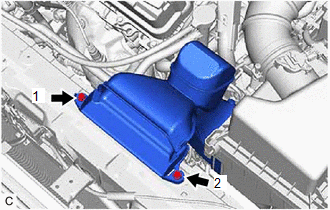
40. INSTALL BATTERY CLAMP SUB-ASSEMBLY (a) Install the battery clamp sub-assembly with the 3 bolts. Torque: 18.5 N·m {189 kgf·cm, 14 ft·lbf} (b) Engage the 5 clamps to the battery clamp sub-assembly. 41. INSTALL BATTERY Click here 42. CONNECT ENGINE ROOM MAIN WIRE (a) Connect the engine wire with engine room main wire to the positive (+) battery terminal with the nut. Torque: 7.6 N·m {77 kgf·cm, 67 in·lbf} 43. INSTALL ECM Click here
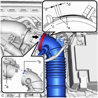
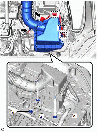
44. INSTALL AIR CLEANER ASSEMBLY WITH AIR CLEANER HOSE
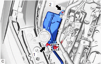
(b) Tighten the hose clamp in the position shown in the illustration. NOTICE: Make sure that the end of the hose clamp is positioned as shown in the illustration.
(d) Engage the vacuum hose to the air cleaner hose. (e) Engage the 3 wire harness clamps. (f) Connect the mass air flow meter sub-assembly connector.
(h) Engage the 2 clamps to connect the No. 1 fuel vapor feed hose to the air cleaner hose. 45. INSTALL INLET AIR CLEANER ASSEMBLY
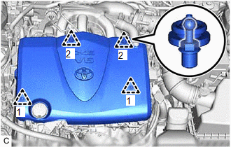
46. INSTALL V-BANK COVER SUB-ASSEMBLY
47. INSPECT VACUUM HOSES (a) Inspect the vacuum hoses. 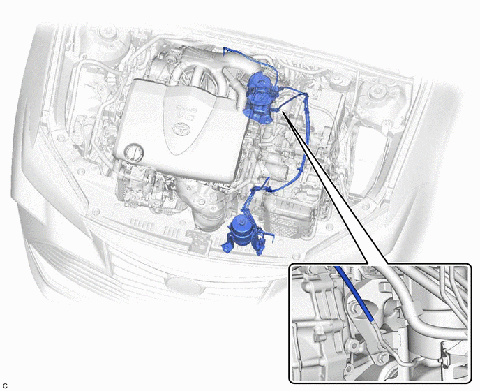 48. CONNECT CABLE TO NEGATIVE BATTERY TERMINAL NOTICE: When disconnecting the cable, some systems need to be initialized after the cable is reconnected. Click here 49. ADD ENGINE OIL Click here
50. ADD ENGINE COOLANT Click here
51. ADD AUTOMATIC TRANSAXLE FLUID Click here 52. CHARGE AIR CONDITIONING SYSTEM WITH REFRIGERANT Click here 53. WARM UP ENGINE Click here
54. INSPECT SHIFT LEVER POSITION Click here
55. ADJUST SHIFT LEVER POSITION Click here
56. INSPECT FOR ENGINE OIL LEAK Click here
57. INSPECT FOR COOLANT LEAK Click here
58. INSPECT FOR REFRIGERANT LEAK Click here
59. INSPECT FOR FUEL LEAK Click here
60. INSPECT FOR EXHAUST GAS LEAK Click here
61. CHECK ENGINE OIL LEVEL Click here
62. INSPECT ENGINE COOLANT LEVEL IN RESERVOIR TANK Click here 63. INSTALL FRONT LOWER BUMPER ABSORBER (a) Engage the 2 claws to the front lower bumper absorber. (b) Install the 4 bolts. Torque: 7.5 N·m {76 kgf·cm, 66 in·lbf} 64. INSTALL FRONT BUMPER COVER Click here 65. INSTALL FRONT FENDER APRON SEAL LH (a) Install the front fender apron seal LH with the 2 screws and clip. Torque: 7.5 N·m {76 kgf·cm, 66 in·lbf} 66. INSTALL FRONT FENDER APRON SEAL RH (a) Install the front fender apron seal RH with the 2 screws and clip. Torque: 7.5 N·m {76 kgf·cm, 66 in·lbf} 67. INSTALL REAR ENGINE UNDER COVER RH (a) Install the rear engine under cover RH with the 2 screws and 3 clips. Torque: 7.5 N·m {76 kgf·cm, 66 in·lbf} 68. INSTALL REAR ENGINE UNDER COVER LH (a) Install the rear engine under cover LH with the 2 screws and 3 clips. Torque: 7.5 N·m {76 kgf·cm, 66 in·lbf} 69. INSTALL NO. 1 ENGINE UNDER COVER (a) Install the No. 1 engine under cover with the bolt, 6 screws and 2 clips. Torque: Bolt : 7.5 N·m {76 kgf·cm, 66 in·lbf} 70. INSTALL FRONT WHEEL OPENING EXTENSION PAD LH (a) Install the front wheel opening extension pad LH with the 3 screws. 71. INSTALL FRONT WHEEL OPENING EXTENSION PAD RH (a) Install the front wheel opening extension pad RH with the 3 screws. 72. INSTALL FRONT WHEELS Click here 73. ALIGN FRONT WHEELS FACING STRAIGHT AHEAD 74. INSPECT AND ADJUST FRONT WHEEL ALIGNMENT Click here 75. PERFORM INITIALIZATION Click here 76. INSPECT IGNITION TIMING Click here 77. INSPECT ENGINE IDLE SPEED Click here 78. INSPECT CO/HC Click here
79. CHECK FOR SPEED SENSOR SIGNAL Click here |
Toyota Avalon (XX50) 2019-2022 Service & Repair Manual > Power Window Control System(for Hv Model): How To Proceed With Troubleshooting
CAUTION / NOTICE / HINT HINT: Use the following procedure to troubleshoot the power window control system. *: Use the Techstream. PROCEDURE 1. VEHICLE BROUGHT TO WORKSHOP NEXT 2. CUSTOMER PROBLEM ANALYSIS HINT: In troubleshooting, confirm that the problem symptoms have been accurately identified. Pr ...