Toyota Avalon (XX50) 2019-2022 Service & Repair Manual: Removal

REMOVAL

CAUTION / NOTICE / HINT

The necessary procedures (adjustment, calibration, initialization or registration) that must be performed after parts are removed and installed, or replaced during engine assembly removal/installation are shown below.

Necessary Procedure After Parts Removed/Installed/Replaced

Replaced Part or Performed Procedure

Necessary Procedure

Effect/Inoperative Function when Necessary Procedure not Performed

Link

Battery terminal is disconnected/reconnected

Perform steering sensor zero point calibration

Lane departure alert system (w/ Steering Control)

Pre-collision system

Intelligent Clearance Sonar System*1

Lighting System (for Gasoline Model with Cornering Light)

Memorize steering angle neutral point

Parking Assist Monitor System

Panoramic View Monitor System

Replacement of ECM

Vehicle Identification Number (VIN) registration

MIL comes on

ECU communication ID registration (Immobiliser system)

Engine start function

  • Replacement of engine assembly
  • Gas leak from exhaust system is repaired

Inspection after repair

  • Poor idle, etc.
  • Engine start function, etc.

Replacement of automatic transaxle assembly

  • Perform reset memory
  • Input transaxle compensation code into ECM
  • Perform road test to allow ECM to learn
  • Large shift shock
  • Deterioration of fuel efficiency

for Initialization

for Registration

Replacement of ECM

(If transaxle compensation code read from ECM)

  • Perform reset memory*2
  • Transfer transaxle compensation code
  • Perform road test to allow ECM to learn

Replacement of ECM

(If transaxle compensation code not read from ECM)

  • Perform reset memory*2
  • Reset transaxle compensation code
  • Perform road test to allow ECM to learn

Replacement of automatic transaxle fluid

ATF thermal degradation estimate reset

The value of the Data List item "ATF Thermal Degradation Estimate" is not estimated correctly

Replacement of ECM

Code registration (Smart Key System (for Start Function))

  • Wireless Door Lock Control System
  • Smart Key System (for Entry Function)
  • Smart Key System (for Start Function)
  • Steering lock function

Suspension, tires, etc.

  • Measure ultrasonic sensor detection angle
  • Ultrasonic sensor detection angle registration
  • Intelligent Clearance Sonar System
  • Intuitive Parking Assist System

Rear television camera assembly optical axis adjustment (Back camera position setting)

Parking Assist Monitor System

for Initialization

for Calibration

  • Parking assist ECU initialization
  • Adjust steering angle
  • Television camera assembly optical axis adjustment (Back camera position setting)

Panoramic View Monitor System

for Initialization

for Calibration

Perform headlight ECU sub-assembly LH initialization

Lighting system (for Gasoline Model with Cornering Light)

Front wheel alignment adjustment

Perform system variant learning and acceleration sensor zero point calibration.

  • VSC is disabled or malfunctions
  • DTCs are output
  • Slip indicator light illuminates
  • ABS warning light illuminates

  • *1: When performing learning using the Techstream.

    Click here

  • *2: Not necessary when ECM replaced with new one.

CAUTION:

  • The engine assembly with transaxle is very heavy. Be sure to follow the procedure described in the repair manual, or the engine lifter may suddenly drop or the engine assembly with transaxle may fall off the engine lifter.

    *a

    An Object Exceeding Weight Limit of Engine Lifter

  • To prevent burns, do not touch the engine, exhaust manifold or other high temperature components while the engine is hot.

PROCEDURE

1. PRECAUTION

NOTICE:

After turning the engine switch off, waiting time may be required before disconnecting the cable from the negative (-) battery terminal. Therefore, make sure to read the disconnecting the cable from the negative (-) battery terminal notices before proceeding with work.

Click here

2. RECOVER REFRIGERANT FROM REFRIGERATION SYSTEM

Click here

3. DISCHARGE FUEL SYSTEM PRESSURE

Click here

4. DISCONNECT CABLE FROM NEGATIVE BATTERY TERMINAL

NOTICE:

When disconnecting the cable, some systems need to be initialized after the cable is reconnected.

Click here

5. ALIGN FRONT WHEELS FACING STRAIGHT AHEAD

6. SECURE STEERING WHEEL

Click here

7. REMOVE FRONT WHEEL OPENING EXTENSION PAD LH

(a) Remove the 3 screws and front wheel opening extension pad LH.

8. REMOVE FRONT WHEEL OPENING EXTENSION PAD RH

(a) Remove the 3 screws and front wheel opening extension pad RH.

9. REMOVE NO. 1 ENGINE UNDER COVER

(a) Remove the bolt, 2 clips, 6 screws and No. 1 engine under cover.

10. REMOVE REAR ENGINE UNDER COVER LH

(a) Remove the 2 screws, 3 clips and rear engine under cover LH.

11. REMOVE REAR ENGINE UNDER COVER RH

(a) Remove the 2 screws, 3 clips and rear engine under cover RH.

12. REMOVE FRONT FENDER APRON SEAL LH

(a) Remove the 2 screws, clip and front fender apron seal LH from the vehicle body.

13. REMOVE FRONT FENDER APRON SEAL RH

(a) Remove the 2 screws, clip and front fender apron seal RH from the vehicle body.

14. REMOVE FRONT BUMPER COVER

Click here

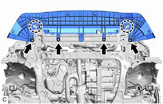
15. REMOVE FRONT LOWER BUMPER ABSORBER

(a) Remove the 4 bolts.

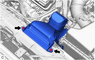
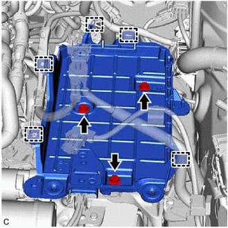
(b) Disengage the 2 claws to remove the front lower bumper absorber.

16. DRAIN ENGINE COOLANT

Click here

17. DRAIN ENGINE OIL

Click here

18. DRAIN AUTOMATIC TRANSAXLE FLUID

Click here

19. REMOVE V-BANK COVER SUB-ASSEMBLY

(a) Disengage the 4 clips in the order shown in the illustration and lift the V-bank cover sub-assembly upward to remove it.
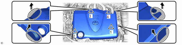
Hold here

Pull in this Direction

NOTICE:

  • Pull the V-bank cover sub-assembly straight up to remove it.
  • Do not remove the V-bank cover sub-assembly in any direction other than upward. If the V-bank cover sub-assembly is removed in any direction other than upward, it may be damaged.
  • If the clips are not disengaged in the order shown in the illustration, the V-bank cover sub-assembly may be damaged.

20. REMOVE INLET AIR CLEANER ASSEMBLY

(a) Remove the 2 bolts and inlet air cleaner assembly.

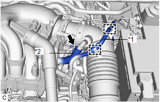
21. REMOVE AIR CLEANER ASSEMBLY WITH AIR CLEANER HOSE

(a) Disengage the 2 clamps to disconnect the No. 1 fuel vapor feed hose from the air cleaner hose.

*1

No. 1 Fuel Vapor Feed Hose

*2

No. 2 Ventilation Hose

(b) Slide the clip and disconnect the No. 2 ventilation hose from the air cleaner hose.

(c) Loosen the hose clamp.

(d) Disconnect the mass air flow meter sub-assembly connector.

*a

Pin

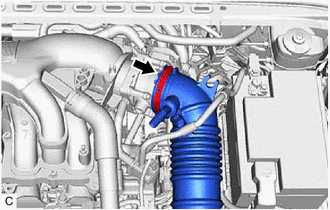
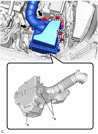
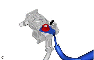
(e) Disengage the 3 wire harness clamps.

(f) Disconnect the vacuum hose from the air cleaner hose.

(g) Disengage the 3 pins and remove the air cleaner assembly with air cleaner hose.

NOTICE:

Make sure the air cleaner support remains attached to the vehicle body.

22. REMOVE ECM

Click here

23. DISCONNECT ENGINE ROOM MAIN WIRE

(a) Remove the nut and disconnect the engine wire with engine room main wire from the positive (+) battery terminal.

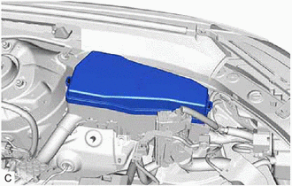
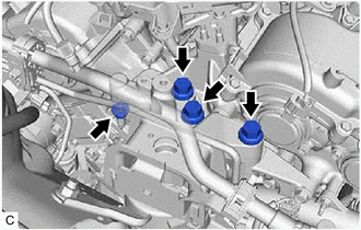
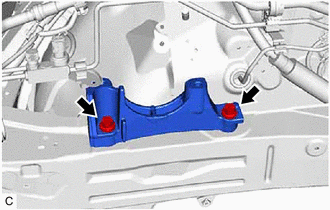
24. REMOVE BATTERY

Click here

25. REMOVE BATTERY CLAMP SUB-ASSEMBLY

(a) Disengage the 5 clamps from the battery clamp sub-assembly.

(b) Remove the 3 bolts and battery clamp sub-assembly.

26. DISCONNECT TRANSMISSION CONTROL CABLE ASSEMBLY

(a) While disengaging the clip as shown in the illustration, disconnect the transmission control cable assembly from the transmission control shaft lever together with the clip.

*a

Clip

*b

45° to 60°

(b) Remove the clip and disconnect the transmission control cable assembly from the No. 1 transmission control cable bracket.

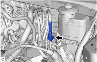
27. DISCONNECT NO. 1 FUEL VAPOR FEED HOSE

(a) Slide the clip and disconnect the No. 1 fuel vapor feed hose from the No. 1 vacuum switching valve assembly.

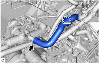
28. DISCONNECT UNION TO CHECK VALVE HOSE

(a) Slide the clip and disconnect the union to check valve hose from the brake booster assembly.

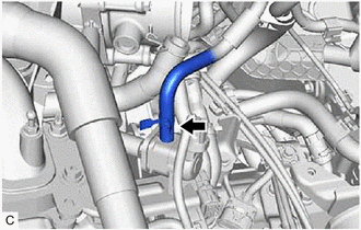
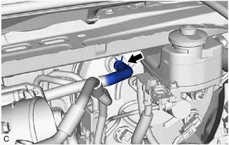
29. DISCONNECT NO. 2 RADIATOR HOSE

(a) Slide the clip and disconnect the No. 2 radiator hose from the water inlet.

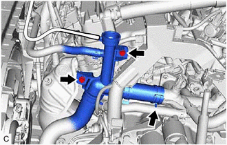
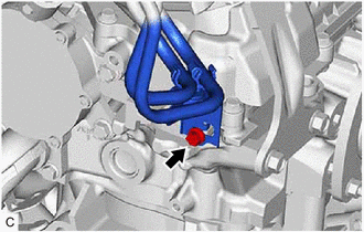
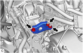
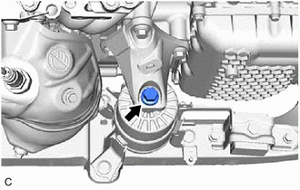
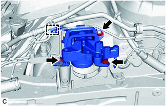
30. SEPARATE RADIATOR HOSE SUB-ASSEMBLY

(a) Slide the clip and disconnect the radiator hose sub-assembly from the water outlet.

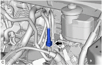
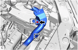
(b) Remove the 2 bolts and separate the radiator hose sub-assembly from the engine assembly.

31. DISCONNECT INLET HEATER WATER HOSE

(a) Disengage the clamp.

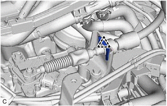
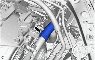
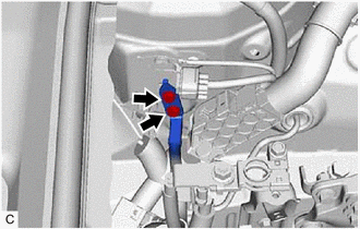
(b) Slide the clip and disconnect the inlet heater water hose from the water outlet.

32. DISCONNECT OUTLET HEATER WATER HOSE

(a) Slide the clip and disconnect the outlet heater water hose from the heater water pipe.

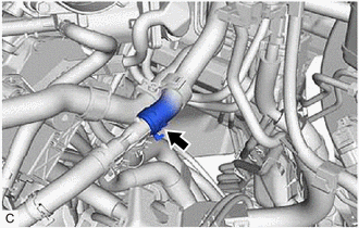
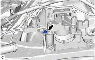
33. DISCONNECT NO. 1 FUEL HOSE

(a) Disengage the 2 claws to remove the No. 2 fuel pipe clamp.

(b) Remove the No. 1 fuel pipe clamp from the fuel tube connector.

(c) Disconnect the No. 1 fuel hose (for Port Injection).

(1) Disconnect the No. 1 fuel hose from the fuel pipe.

Click here

(d) Disconnect the No. 1 fuel hose (for Direct Injection).

(1) Disconnect the No. 1 fuel hose from the fuel pipe.

Click here

(e) Separate the bolt and disengage the No. 1 fuel hose.

34. DISCONNECT NO. 1 COOLER REFRIGERANT DISCHARGE HOSE SUB-ASSEMBLY

Click here

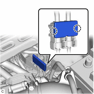
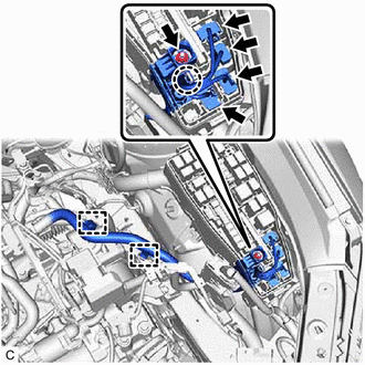
35. DISCONNECT SUCTION HOSE SUB-ASSEMBLY

Click here

36. DISCONNECT ENGINE WIRE

HINT:

After disconnecting the engine wire, secure it with tape or equivalent to keep it out of the way.

(a) Remove the No. 2 relay block cover from the engine room relay block and junction block assembly.

(b) Remove the nut from the engine room relay block and junction block assembly.

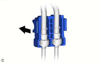
(c) Disconnect the 4 connectors from the engine room relay block and junction block assembly.

(d) Disengage the 2 clamps.

(e) Using a screwdriver, disengage the claw and disconnect the engine wire from the engine room relay block and junction block assembly.

(f) Remove the bolt.

(g) Disengage the 2 clamps and disconnect the engine wire from the vehicle body.

37. DISCONNECT EARTH WIRE

(a) Remove the 2 bolts and disconnect the earth wire from the vehicle body.

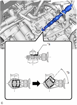
38. SEPARATE STEERING INTERMEDIATE SHAFT ASSEMBLY

Click here

39. REMOVE EXHAUST MANIFOLD

Click here

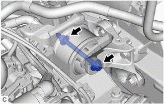
40. REMOVE FRONT DRIVE SHAFT ASSEMBLY

Click here

41. REMOVE NO. 1 EXHAUST PIPE SUPPORT BRACKET (for Upper Side)

(a) Remove the 2 bolts and No. 1 exhaust pipe support bracket from the oil pan sub-assembly.

42. REMOVE FLYWHEEL HOUSING UNDER COVER

(a) Remove the 2 bolts and flywheel housing under cover.

43. REMOVE DRIVE PLATE AND TORQUE CONVERTER ASSEMBLY SETTING BOLT

Click here

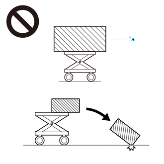
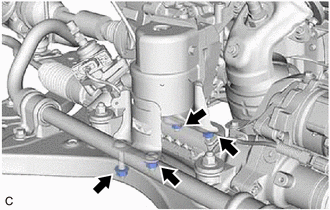
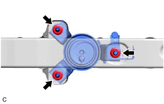
44. REMOVE ENGINE ASSEMBLY WITH TRANSAXLE

(a) Set an engine lifter.

NOTICE:

  • Using height adjustment attachments and plate lift attachments, keep the engine assembly with transaxle level.
  • Do not perform any procedures while the engine assembly is suspended because doing so may cause the engine assembly to drop, resulting in injury. However, the engine assembly needs to be suspended when it is installed to or removed from an engine stand.
  • To prevent the engine assembly from unexpectedly moving, securely support the engine assembly until it is secured to an engine stand.
  • To prevent the No. 2 oil pan sub-assembly from deforming, do not place any attachments under the No. 2 oil pan sub-assembly of the engine assembly with transaxle.

(b) Remove the bolt, 2 nuts and No. 2 engine mounting stay RH.

(c) Remove the 3 bolts and nut and separate the engine mounting insulator sub-assembly RH from the front No. 1 engine mounting bracket LH.

(d) Remove the bolt and nut and separate the engine mounting insulator LH from the engine mounting bracket sub-assembly LH.

Bolt

Nut

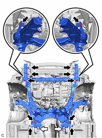
(e) Remove the 8 bolts and front bumper extension sub-assembly RH and front bumper extension sub-assembly LH from the front frame assembly and vehicle body.

(f) Remove the 4 bolts, 2 nuts and front suspension member bracket sub-assembly RH and front suspension member bracket sub-assembly LH from the front frame assembly and vehicle body.

(g) Operate the engine lifter and remove the engine assembly with transaxle from the vehicle.

NOTICE:

  • Make sure that the engine assembly with transaxle is clear of all wiring and hoses.
  • While lowering the engine assembly with transaxle from the vehicle, do not allow it to contact the vehicle.

45. DISCONNECT VACUUM HOSE

Click here

46. REMOVE STARTER ASSEMBLY

Click here

47. REMOVE BREATHER PLUG HOSE

Click here

48. DISCONNECT NO. 1 WATER BY-PASS HOSE

Click here

49. DISCONNECT WATER BY-PASS HOSE ASSEMBLY

Click here

50. REMOVE ENGINE WIRE

(a) Disconnect all clamps and connectors and remove the engine wire from the engine assembly with transaxle.

51. INSTALL ENGINE HANGERS

(a) Install the No. 1 engine hanger and No. 2 engine hanger with the 4 bolts as shown in the illustration.

Torque:

33 N·m {337 kgf·cm, 24 ft·lbf}

No. 1 Engine Hanger

12281-31121

No. 2 Engine Hanger

12282-31100

Bolt

90119-A0117

*A

for Bank 1

*B

for Bank 2

*1

No. 1 Engine Hanger

*2

No. 2 Engine Hanger

(b) Using an engine sling device and engine lifter, secure the engine assembly with transaxle.

NOTICE:

  • Adjust the angle of the sling device carefully to prevent damage or deformation to the engine hangers or engine assembly.
  • Do not perform any procedures while the engine assembly is suspended because doing so may cause the engine assembly to drop, resulting in injury. However, the engine assembly needs to be suspended when it is installed to or removed from an engine stand.

52. REMOVE FRONT FRAME ASSEMBLY

(a) Remove the bolt and separate the front engine mounting insulator from the front engine mounting bracket.

(b) Remove the 4 nuts and separate the rear engine mounting insulator from the front frame assembly.

53. REMOVE FRONT ENGINE MOUNTING INSULATOR

HINT:

Perform this procedure only when replacement of the front engine mounting insulator is necessary.

(a) Remove the 3 nuts and front engine mounting insulator from the front frame assembly.

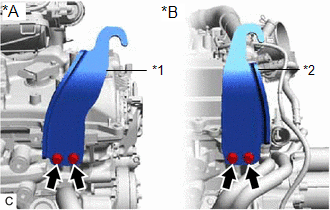
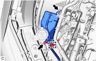
54. REMOVE REAR ENGINE MOUNTING INSULATOR

HINT:

Perform this procedure only when replacement of the rear engine mounting insulator is necessary.

Click here

55. REMOVE FRONT ENGINE MOUNTING BRACKET

Click here

56. REMOVE AUTOMATIC TRANSAXLE ASSEMBLY

Click here

57. REMOVE DRIVE PLATE AND RING GEAR SUB-ASSEMBLY

Click here

58. REMOVE NO. 1 CRANKSHAFT POSITION SENSOR PLATE

Click here

59. INSTALL ENGINE ASSEMBLY TO ENGINE STAND

(a) Install the engine assembly to an engine stand.

60. REMOVE ENGINE HANGERS

(a) Remove the 4 bolts, No. 1 engine hanger and No. 2 engine hanger from the cylinder head sub-assembly and cylinder head LH.

61. REMOVE ENGINE MOUNTING INSULATOR SUB-ASSEMBLY RH

HINT:

Perform this procedure only when replacement of the engine mounting insulator sub-assembly RH is necessary.

(a) Disengage the clamp.

(b) Remove the bolt, nut and separate the radiator reserve tank assembly.

(c) Remove the bolt and separate the bracket from the engine mounting insulator sub-assembly RH.

(d) Disengage the clamp.

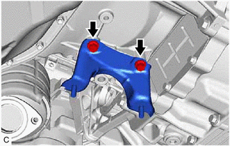
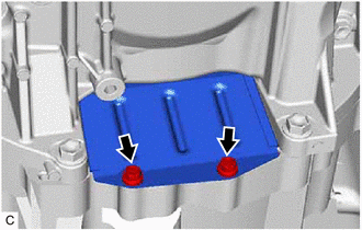
(e) Remove the nut, 2 bolts and engine mounting insulator sub-assembly RH from the engine mounting spacer and vehicle body.

62. REMOVE ENGINE MOUNTING SPACER

HINT:

Perform this procedure only when replacement of the engine mounting spacer is necessary.

(a) Remove the 2 bolts and engine mounting spacer from the vehicle body.

63. REMOVE ENGINE MOUNTING BRACKET SUB-ASSEMBLY LH

HINT:

Perform this procedure only when replacement of the engine mounting bracket sub-assembly LH is necessary.

(a) Remove the 4 bolts and engine mounting bracket sub-assembly LH from the vehicle body.

64. REMOVE ENGINE MOUNTING INSULATOR LH

HINT:

Perform this procedure only when replacement of the engine mounting insulator LH is necessary.

Click here

    Installation

    Engine Unit

    See More:

    Toyota Avalon (XX50) 2019-2022 Service & Repair Manual > Dynamic Radar Cruise Control System(for Hv Model): Vehicle Information Not Obtained (C1A02)
    DESCRIPTION When a new driving support ECU assembly is installed, it receives vehicle specification information (destination, steering wheel position, 2WD or AWD, etc.) from the main body ECU (multiplex network body ECU) and stores the information. DTC C1A02 is stored when the driving support ECU as ...

    Toyota Avalon (XX50) 2019-2022 Owners Manual

    Toyota Avalon (XX50) 2019-2022 Service & Repair Manual

    © 2024 Copyright www.tavalon.net
    0.0177