ON-VEHICLE INSPECTION CAUTION / NOTICE / HINT  CAUTION: To prevent injury due to contact with an operating V-ribbed belt or cooling fan, keep your hands and clothing away from the V-ribbed belt and cooling fans when working in the engine compartment with the engine running or the engine switch on (IG). PROCEDURE 1. INSPECT ENGINE COOLANT Click here 2. INSPECT ENGINE OIL Click here 3. CHECK BATTERY CONDITION Click here 4. INSPECT SPARK PLUG Click here 5. INSPECT AIR CLEANER FILTER ELEMENT SUB-ASSEMBLY (a) Remove the air cleaner filter element sub-assembly. (b) Visually check that the air cleaner filter element sub-assembly is not damaged or excessively oily. HINT:
(c) Install the air cleaner filter element sub-assembly. 6. INSPECT V-RIBBED BELT Click here 7. INSPECT V-RIBBED BELT TENSIONER ASSEMBLY (a) Remove the V-ribbed belt. Click here
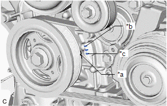
(b) Turn the V-ribbed belt tensioner assembly clockwise and counterclockwise and check that it turns smoothly and does not catch. HINT: If the V-ribbed belt tensioner assembly does not turn smoothly or catches, replace the V-ribbed belt tensioner assembly. (c) Install the V-ribbed belt. Click here
8. INSPECT VALVE LASH ADJUSTER ASSEMBLY NOISE (a) Rev up the engine several times. Check that the engine does not emit unusual noises. (b) If unusual noises occur, warm up the engine and idle it for 30 minutes or more, then perform the inspection. HINT: If any defects or problems are found during the inspection, perform valve lash adjuster assembly inspection. Click here 9. INSPECT IGNITION TIMING NOTICE:
(a) Warm up and stop the engine. (b) When using the Techstream: (1) Connect the Techstream to the DLC3. (2) Start the engine and run it at idle. (3) Turn the Techstream on. (4) Enter the following menus: Powertrain / Engine / Data List / Ignition Timing Cylinder #1 Powertrain > Engine > Data List
Standard Ignition Timing: 12 to 24° BTDC at idle (5) Check that the ignition timing advances immediately when the engine speed is increased. (6) Enter the following menus: Powertrain / Engine / Active Test / Activate the TC Terminal / ON. Powertrain > Engine > Active Test
(7) Monitor Ignition Timing Cylinder #1 of the Data List. Standard Ignition Timing: 8 to 12° BTDC at idle (c) When not using the Techstream:
(2) Remove the front wheel RH. Click here
(3) Remove the front fender apron seal RH. Click here
(5) Start the engine and run it at idle.
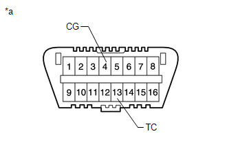
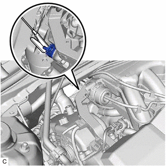
(7) Disconnect terminals 13 (TC) and 4 (CG) of the DLC3. (8) Check the ignition timing at idle. Standard Ignition Timing: 12 to 24° BTDC at idle (9) Confirm that the ignition timing advances immediately when the engine speed is increased. (10) Disconnect the clip of the timing light from the ignition coil wire for the No. 1 cylinder. (11) Install the front fender apron seal RH. Click here
(12) Install the front wheel RH. Click here
10. INSPECT ENGINE IDLE SPEED NOTICE:
(a) Warm up and stop the engine. (b) Connect the Techstream to the DLC3. (c) Start the engine and run it at idle. (d) Turn the Techstream on. (e) Enter the following menus: Powertrain / Engine / Data List / Engine Speed. Powertrain > Engine > Data List
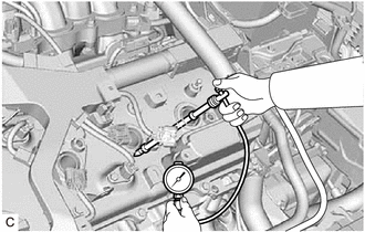
(f) Read the value displayed on the Techstream. Standard Idle Speed: 600 to 700 rpm 11. INSPECT COMPRESSION NOTICE: Keep the spark plug holes free of foreign matter when measuring the compression pressure. (a) Warm up and stop the engine. (b) Check for DTCs. Click here
(c) Remove the 6 spark plugs. Click here
(e) Install the 6 spark plugs. Click here
(f) Clear the DTCs. Click here
NOTICE: After the inspection, clear the DTCs, check for DTCs again and make sure the normal system code is output. 12. INSPECT CO/HC HINT: This check determines whether or not the idle CO/HC complies with regulations. (a) Start the engine. (b) Run the engine speed at 2500 rpm for approximately 180 seconds. (c) Insert a CO/HC meter testing probe at least 40 cm (1.31 ft.) into the tailpipe during idle. (d) Immediately check the CO/HC concentration at idle and then at an engine speed of 2500 rpm. HINT: When performing a 2 mode test (with the engine idling/running at 2500 rpm), the measurement procedures are determined by applicable local regulations. If the CO/HC concentration does not comply with the regulations, perform troubleshooting in the order given below. (1) Check for DTCs. Click here (2) See the following table for possible causes, then inspect the applicable parts and repair them if necessary.
|
Toyota Avalon (XX50) 2019-2022 Service & Repair Manual > Sfi System: HO2S Heater Control Circuit Bank 1 Sensor 2 Circuit Short to Battery (P003612,P003613,P102A9E)
DESCRIPTION The air fuel ratio sensor (sensor 2) generates current that corresponds to the actual air fuel ratio. This sensor current is used to provide the ECM with feedback so that it can control the air fuel ratio. The ECM determines the deviation from the stoichiometric air fuel ratio level, and ...