Components COMPONENTS ILLUSTRATION 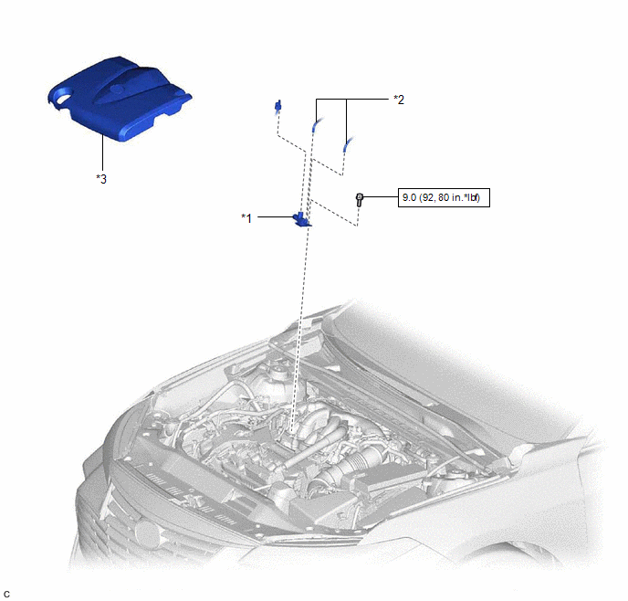
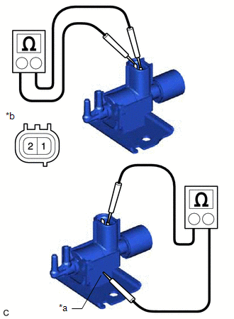
Inspection INSPECTION PROCEDURE 1. INSPECT NO. 1 VACUUM SWITCHING VALVE ASSEMBLY (for ACIS)
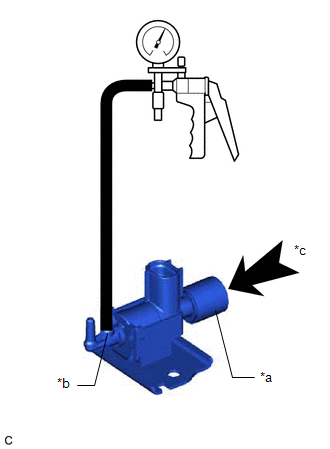
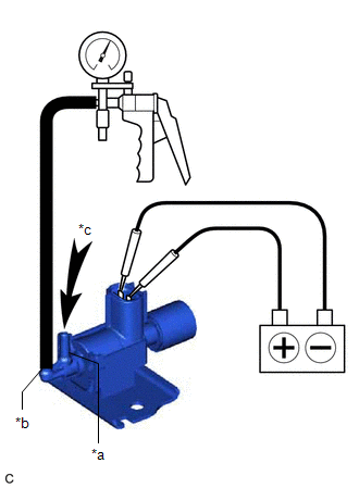
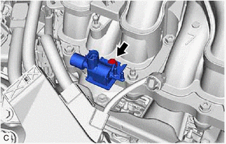
(b) Check the No. 1 vacuum switching valve assembly (for ACIS) operation.
Installation INSTALLATION PROCEDURE 1. INSTALL NO. 1 VACUUM SWITCHING VALVE ASSEMBLY (for ACIS) (a) Install the No. 1 vacuum switching valve assembly (for ACIS) to the intake air surge tank assembly with the bolt. Torque: 9.0 N·m {92 kgf·cm, 80 in·lbf} (b) Connect the 2 vacuum hose sub-assemblies to the No. 1 vacuum switching valve assembly (for ACIS). (c) Connect the No. 1 vacuum switching valve assembly (for ACIS) connector. 2. INSTALL V-BANK COVER SUB-ASSEMBLY Click here
Removal REMOVAL PROCEDURE 1. REMOVE V-BANK COVER SUB-ASSEMBLY Click here
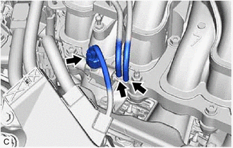
2. REMOVE NO. 1 VACUUM SWITCHING VALVE ASSEMBLY (for ACIS)
(b) Disconnect the 2 vacuum hose assemblies from the No. 1 vacuum switching valve assembly (for ACIS).
|
Toyota Avalon (XX50) 2019-2022 Service & Repair Manual > Electronically Controlled Brake System(for Hv Model): Yaw Rate Sensor discrimination (C1240)
DESCRIPTION The airbag ECU assembly has a built-in yaw rate and acceleration sensor and detects the vehicle condition using 2 circuits (GL1, GL2). If the identification ID of the yaw rate and acceleration sensor (airbag ECU assembly) is different to that stored in the skid control ECU (brake booster ...