Toyota Avalon (XX50) 2019-2022 Service & Repair Manual: Inspection

INSPECTION

PROCEDURE

1. INSPECT STARTER ASSEMBLY

CAUTION:

As a large electric current passes through the cable during this inspection, a thick cable must be used. If not, the cable may become hot and cause injury.

NOTICE:

Perform each of the following tests within 3 to 5 seconds to prevent the coil from burning out.

(a) Perform a pull-in test.

(1) Remove the nut, and disconnect the field coil lead wire from terminal C.

(2) Connect a battery to the magnet starter switch assembly as shown in the illustration. Check that the clutch pinion gear moves outward.

If the clutch pinion gear does not move outward, replace the magnet starter switch assembly.

*a

Terminal 50

*b

Terminal C

*c

Starter Body

Moves outward

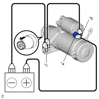
(b) Perform a hold-in test.

(1) While maintaining the battery connections of the pull-in test, disconnect the negative (-) lead from terminal C. Check that the clutch pinion gear does not return inward.

*a

Terminal 50

*b

Terminal C

*c

Starter Body

Disconnect

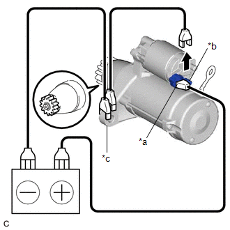
If the clutch pinion gear returns inward, replace the magnet starter switch assembly.

(c) Perform a return test.

(1) Disconnect the negative (-) lead from the starter body. Check that the clutch pinion gear returns inward.

*a

Terminal 50

*b

Terminal C

*c

Starter Body

Disconnect

Returns inward

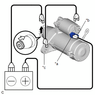
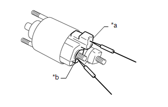
If the clutch pinion gear does not return inward, replace the magnet starter switch assembly.

(d) Perform a no-load performance test.

(1) Connect the field coil lead wire to terminal C with the nut. Make sure that the field coil lead wire is not grounded.

Torque:

10 N·m {102 kgf·cm, 7 ft·lbf}

(2) Secure the starter assembly in a vise between aluminum plates.

NOTICE:

Ensure that the starter assembly is secured in the vise to prevent it from falling out.

*a

Terminal 50

*b

Terminal 30

*c

Starter Body

Rotates

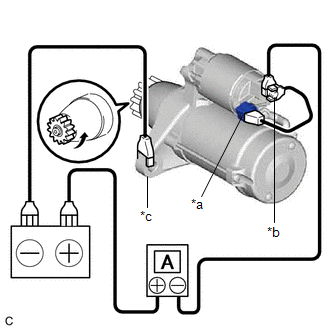
(3) Connect the battery and an ammeter to the starter assembly as shown in the illustration.

NOTICE:

Do not allow any lead to get caught as the clutch pinion gear operates.

(4) Check that the starter assembly operates smoothly and steadily while the clutch pinion gear is moving outward.

Measure the current according to the value(s) in the table below.

Standard Current:

Tester Connection

Condition

Specified Condition

Battery positive (+) terminal - Terminal 30 - Terminal 50

11.5 V

Below 90 A

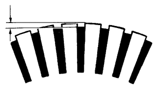
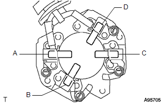
If the result is not as specified, replace the starter assembly.

2. INSPECT STARTER ARMATURE ASSEMBLY

HINT:

If there is no continuity between any segments, replace the starter armature assembly.

(a) Check the commutator appearance.

If the surface is dirty or burnt, restore it with sandpaper (400-grit) or on a lathe.

(b) Check the commutator for an open circuit.

(1) Measure the resistance according to the value(s) in the table below.

Standard Resistance:

Tester Connection

Condition

Specified Condition

Segment - Segment

Always

Below 1 Ω

If the result is not as specified, replace the starter armature assembly.

*a

Segment

(c) Check the commutator for a short circuit.

(1) Measure the resistance according to the value(s) in the table below.

Standard Resistance:

Tester Connection

Condition

Specified Condition

Segment - Starter armature core

Always

10 kΩ or higher

If the result is not as specified, replace the starter armature assembly.

*a

Segment

*b

Starter Armature Core

(d) Check the commutator for runout.

(1) Place the armature shaft on V-blocks.

(2) Using a dial indicator, measure the runout.

Maximum Runout:

0.05 mm (0.00197 in.)

If the runout is greater than the maximum, replace the starter armature assembly.

*a

Armature Shaft

(e) Using a vernier caliper, measure the commutator diameter.

Standard Diameter:

29 mm (1.14 in.)

Minimum Diameter:

28 mm (1.10 in.)

If the diameter is less than the minimum, replace the starter armature assembly.

(f) Check that the undercut portion between the segments is free of foreign matter and measure its depth.

Standard Undercut Depth:

0.7 mm (0.0276 in.)

Minimum Undercut Depth:

0.2 mm (0.00787 in.)

If the undercut depth is less than the minimum, adjust it with a hacksaw blade.

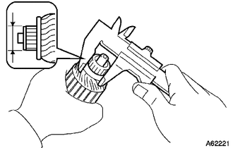
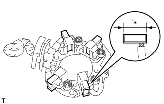
3. INSPECT STARTER BRUSH HOLDER ASSEMBLY

(a) Check the brush length.

(1) Using a vernier caliper, measure the brush length.

Standard Length:

14.4 mm (0.567 in.)

Minimum Length:

9.0 mm (0.354 in.)

If the brush length is less than the minimum, replace the starter brush holder assembly.

*a

Brush Length

(b) Check the brush holder resistance.

(1) Measure the resistance according to the value(s) in the table below.

Standard Resistance:

Tester Connection

Condition

Specified Condition

A - B

A - C

B - D

C - D

Always

10 kΩ or higher

A - D

B - C

Below 1 Ω

If the result is not as specified, replace the starter brush holder assembly.

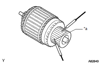
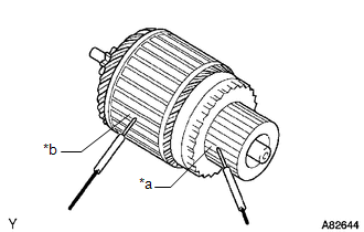
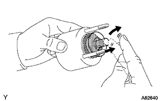
4. INSPECT STARTER CLUTCH

Lock

Free

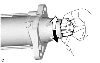
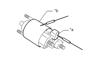
(a) Check the clutch pinion gear.

(1) Rotate the clutch pinion gear counterclockwise and check that it turns freely. Try to rotate the clutch pinion gear clockwise and check that it locks.

If the clutch pinion gear does not operate as specified, replace the repair service starter kit.

5. INSPECT MAGNET STARTER SWITCH ASSEMBLY

(a) Check the plunger.

(1) Push in the plunger and check that it returns quickly to its original position.

If the plunger does not operate as specified, replace the magnet starter switch assembly.

(b) Check the pull-in coil for an open circuit.

(1) Measure the resistance according to the value(s) in the table below.

Standard Resistance:

Tester Connection

Condition

Specified Condition

Terminal 50 - Terminal C

Always

Below 1 Ω

If the result is not as specified, replace the magnet starter switch assembly.

*a

Terminal 50

*b

Terminal C

(c) Check the holding coil for an open circuit.

(1) Measure the resistance according to the value(s) in the table below.

Standard Resistance:

Tester Connection

Condition

Specified Condition

Terminal 50 -Magnet starter switch assembly body

Always

Below 2 Ω

If the result is not as specified, replace the magnet starter switch assembly.

*a

Terminal 50

*b

Magnet Starter Switch Assembly Body

    Disassembly

    Installation

    See More:

    Toyota Avalon (XX50) 2019-2022 Service & Repair Manual > Theft Deterrent System(for Hv Model): System Description
    SYSTEM DESCRIPTION OUTLINE OF THEFT DETERRENT SYSTEM The theft deterrent system can be set/canceled by locking/unlocking the doors using any of the following operations: Entry lock/unlock operation Wireless lock/unlock operation*1 Key linked lock/unlock operation Opening and closing the doors*2 *1: ...

    Toyota Avalon (XX50) 2019-2022 Owners Manual

    Toyota Avalon (XX50) 2019-2022 Service & Repair Manual

    © 2024 Copyright www.tavalon.net
    0.0161