DESCRIPTION The ECM calculates an appropriate cooling fan speed based on the engine coolant temperature, air conditioning switch status, refrigerant pressure, engine speed and vehicle speed, and sends a signal to the cooling fan ECU (fan with motor assembly). The cooling fan ECU (fan with motor assembly) steplessly control the speed of the cooling fan based on the duty cycle signal sent from the ECM. By sending signals to the cooling fan ECU (fan with motor assembly) in accordance with the driving conditions and by controlling the cooling fan speed optimally with the ECM, both high cooling performance and quietness are ensured. WIRING DIAGRAM 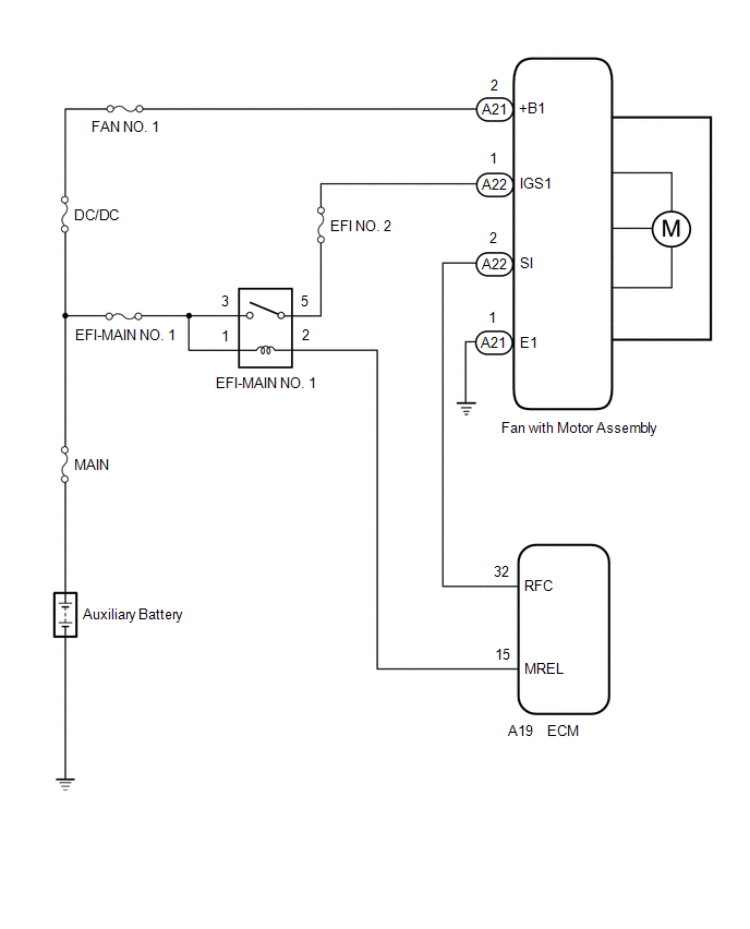 CAUTION / NOTICE / HINT NOTICE:
PROCEDURE
(a) Connect the Techstream to the DLC3. (b) Turn the power switch on (IG). (c) Turn the Techstream on. (d) Enter the following menus: Powertrain / Engine / Active Test / Control the Engine Cooling Fan Duty Ratio. Powertrain > Engine > Active Test
(e) Check the operation of the cooling fan while operating it using the Techstream. OK:
(a) Disconnect the A22 fan with motor assembly connector. (b) Disconnect the A19 ECM connector. (c) Measure the resistance according to the value(s) in the table below. Standard Resistance:
(a) Disconnect the A22 fan with motor assembly connector. (b) Connect the Techstream to the DLC3. (c) Turn the power switch on (IG). (d) Turn the Techstream on. (e) Enter the following menus: Powertrain / Engine / Active Test / Control the Engine Cooling Fan Duty Ratio. Powertrain > Engine > Active Test
(f) Operate the cooling fan motor (fan with motor assembly) using the Active Test function and measure the resistance according to the value(s) in the table below. Standard Resistance:
HINT: *: Using the Active Test, duty control of the transistors in the ECM will be performed. Due to the duty control, resistance of the RFC terminal will be unstable during the Active Test. If the resistance is stable before the Active Test and fluctuates while performing the Active Test, it can be determined that the transistor is operating. If the transistor does not operate during the Active Test, the ECM may be malfunctioning.
(a) Disconnect the A21 fan with motor assembly connector. 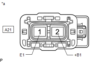
(b) Measure the voltage according to the value(s) in the table below. Standard Voltage:
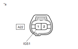
(a) Disconnect the A22 fan with motor assembly connector. (b) Turn the power switch on (IG).
(a) Disconnect the A22 fan with motor assembly connector. (b) Remove the EFI-MAIN NO. 1 relay from the No. 1 engine room relay block and No. 1 junction block assembly. (c) Measure the resistance according to the value(s) in the table below. Standard Resistance:
(a) Disconnect the A21 fan with motor assembly connector. (b) Measure the resistance according to the value(s) in the table below. Standard Resistance:
(a) Disconnect the A22 fan with motor assembly connector. (b) Connect the Techstream to the DLC3. (c) Turn the power switch on (IG). (d) Turn the Techstream on. (e) Enter the following menus: Powertrain / Engine / Active Test / Control the Engine Cooling Fan Duty Ratio. Powertrain > Engine > Active Test
(f) Operate the cooling fan motor (fan with motor assembly) using the Active Test function and measure the resistance according to the value(s) in the table below. Standard Resistance:
HINT: *: Using the Active Test, duty control of the transistors in the ECM will be performed. Due to the duty control, resistance of the RFC terminal will be unstable during the Active Test. If the resistance is stable before the Active Test and fluctuates while performing the Active Test, it can be determined that the transistor is operating. If the transistor does not operate during the Active Test, the ECM may be malfunctioning.
(a) Disconnect the A22 fan with motor assembly connector. (b) Disconnect the A19 ECM connector. (c) Measure the resistance according to the value(s) in the table below. Standard Resistance:
|
Toyota Avalon (XX50) 2019-2022 Service & Repair Manual > Instrument Panel Speaker: Installation
INSTALLATION PROCEDURE 1. INSTALL FRONT NO. 2 SPEAKER ASSEMBLY NOTICE: Do not touch the speaker cone. HINT: Use the same procedure for the RH side and LH side. (a) Connect the connector. (b) Install the front No. 2 speaker assembly with the 2 screws. *A for LH Side *B for RH Side HINT: Install the s ...