DESCRIPTION When the power switch is turned to on (IG), the auxiliary battery voltage is applied to IGSW of the ECM. When the transistor in the MREL circuit operates, current flows from the auxiliary battery to ground through the drive circuit of the EFI-MAIN NO. 1 relay, thus operating the relay which supplies power to the +B and +B2 terminals of the ECM. WIRING DIAGRAM 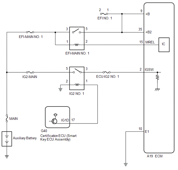 CAUTION / NOTICE / HINT NOTICE: Inspect the fuses for circuits related to this system before performing the following procedure. PROCEDURE
(a) Disconnect the ECM connector. (b) Measure the resistance according to the value(s) in the table below. Standard Resistance:
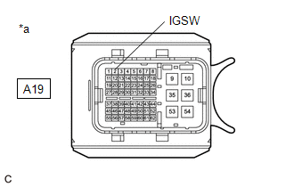
(a) Disconnect the ECM connector. (b) Turn the power switch on (IG). (c) Measure the voltage according to the value(s) in the table below. Standard Voltage:
(a) Inspect the EFI-MAIN NO. 1 relay. Click here
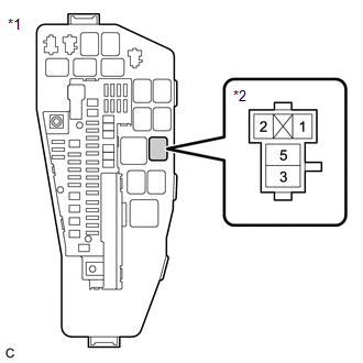
(a) Remove the EFI-MAIN NO. 1 relay from the No. 1 engine room relay block and No. 1 junction block assembly. (b) Remove the VVT, EFI-MAIN NO. 2 and EFI-MAIN NO. 3 relays from the No. 1 engine room relay block and No. 1 junction block assembly. HINT: Remove the VVT, EFI-MAIN NO. 2 and EFI-MAIN NO. 3 relays connected between the checked terminals as the coil inside the relay influences the measurement value. (c) Disconnect the ECM connector. (d) Measure the resistance according to the value(s) in the table below. Standard Resistance:

(a) Remove the EFI-MAIN NO. 1 relay from the No. 1 engine room relay block and No. 1 junction block assembly. (b) Measure the voltage according to the value(s) in the table below. Standard Voltage:
(a) Inspect the IG2 NO. 1 relay. Click here
(a) Remove the IG2 NO. 1 relay from the No. 1 engine room relay block and No. 1 junction block assembly. (b) Disconnect the ECM connector. (c) Measure the resistance according to the value(s) in the table below. Standard Resistance:
(a) Remove the IG2 NO. 1 relay from the No. 1 engine room relay block and No. 1 junction block assembly. (b) Measure the voltage according to the value(s) in the table below. Standard Voltage:
(a) Remove the IG2 NO. 1 relay from the No. 1 engine room relay block and No. 1 junction block assembly. (b) Measure the resistance according to the value(s) in the table below. Standard Resistance:
(a) Disconnect the certification ECU (smart key ECU assembly) connector. (b) Remove the IG2 NO. 1 relay from the No. 1 engine room relay block and No. 1 junction block assembly. (c) Measure the resistance according to the value(s) in the table below. Standard Resistance:
|
Toyota Avalon (XX50) 2019-2022 Service & Repair Manual > Pre-collision System(for Hv Model): Precaution
PRECAUTION HANDLING PRECAUTION FOR PRE-COLLISION SYSTEM (a) In some situations such as the following, the system may determine that there is a possibility of a frontal collision and operate. When passing a vehicle or pedestrian When changing lanes while overtaking a preceding vehicle When overtaking ...


