Toyota Avalon (XX50) 2019-2022 Service & Repair Manual: Radiator Coolant Temperature Sensor Circuit Short to Ground (P00B111)

Toyota Avalon (XX50) 2019-2022 Service & Repair Manual / Engine / A25a-fxs Engine Control / Sfi System / Radiator Coolant Temperature Sensor Circuit Short to Ground (P00B111)

DESCRIPTION

The No. 2 engine coolant temperature sensor is installed to the radiator pipe between the engine and radiator and monitors the thermostat operation.

The structure of the thermistor used in the No. 2 engine coolant temperature sensor and its connection to the ECM are the same as those of the intake air temperature sensor.

Refer to DTC P011011.

Click here

DTC No.

Detection Item

DTC Detection Condition

Trouble Area

MIL

Memory

Note

P00B111

Radiator Coolant Temperature Sensor Circuit Short to Ground

The No. 2 engine coolant temperature sensor output voltage is less than 0.081 V for 3 seconds or more (1 trip detection logic).

  • Short in No. 2 engine coolant temperature sensor circuit
  • No. 2 engine coolant temperature sensor
  • ECM

Comes on

DTC stored

SAE Code: P00B3

MONITOR DESCRIPTION

The No. 2 engine coolant temperature sensor is used to monitor the engine coolant temperature. The No. 2 engine coolant temperature sensor has a thermistor with a resistance that varies according to the temperature of the engine coolant. When the engine coolant temperature is low, the resistance in the thermistor increases. When the temperature is high, the resistance decreases. These variations in resistance are reflected in the output voltage from the sensor. The ECM monitors the sensor voltage and uses this value to calculate the engine coolant temperature. If the No. 2 engine coolant temperature sensor output voltage deviates from the normal operating range, the ECM interprets this as a malfunction of the No. 2 engine coolant temperature sensor circuit, illuminates the MIL and stores a DTC.

Example:

If the No. 2 engine coolant temperature sensor output voltage is less than 0.081 V for 3 seconds or more, the ECM store this DTC.

MONITOR STRATEGY

Related DTCs

P00B3: No. 2 engine coolant temperature sensor range check (low voltage)

Required Sensors/Components (Main)

No. 2 engine coolant temperature sensor

Required Sensors/Components (Related)

-

Frequency of Operation

Continuous

Duration

3 seconds

MIL Operation

Immediate

Sequence of Operation

None

TYPICAL ENABLING CONDITIONS

Monitor runs whenever the following DTCs are not stored

None

Both of the following conditions are met

-

Auxiliary battery voltage

8 V or higher

Power switch

On (IG)

TYPICAL MALFUNCTION THRESHOLDS

No. 2 engine coolant temperature sensor voltage [Engine coolant temperature]

Less than 0.081 V [Higher than 163°C (325°F)]

CONFIRMATION DRIVING PATTERN

HINT:

  • After repair has been completed, clear the DTC and then check that the vehicle has returned to normal by performing the following All Readiness check procedure.

    Click here

  • When clearing the permanent DTCs, refer to the "CLEAR PERMANENT DTC" procedure.

    Click here

  1. Connect the Techstream to the DLC3.
  2. Turn the power switch on (IG).
  3. Turn the Techstream on.
  4. Clear the DTCs (even if no DTCs are stored, perform the clear DTC procedure).
  5. Turn the power switch off and wait for at least 30 seconds.
  6. Turn the power switch on (IG) [A].
  7. Turn the Techstream on.
  8. Wait 3 seconds or more [B].
  9. Enter the following menus: Powertrain / Engine / Trouble Codes [C].
  10. Read the pending DTCs.

    HINT:

    • If a pending DTC is output, the system is malfunctioning.
    • If a pending DTC is not output, perform the following procedure.
  11. Enter the following menus: Powertrain / Engine / Utility / All Readiness.
  12. Input the DTC: P00B111.
  13. Check the DTC judgment result.

    Techstream Display

    Description

    NORMAL

    • DTC judgment completed
    • System normal

    ABNORMAL

    • DTC judgment completed
    • System abnormal

    INCOMPLETE

    • DTC judgment not completed
    • Perform driving pattern after confirming DTC enabling conditions

    HINT:

    • If the judgment result is NORMAL, the system is normal.
    • If the judgment result is ABNORMAL, the system is malfunctioning.
    • [A] to [C]: Normal judgment procedure.

      The normal judgment procedure is used to complete DTC judgment and also used when clearing permanent DTCs.

    • When clearing the permanent DTCs, do not disconnect the cable from the auxiliary battery terminal or attempt to clear the DTCs during this procedure, as doing so will clear the universal trip and normal judgment histories.

WIRING DIAGRAM

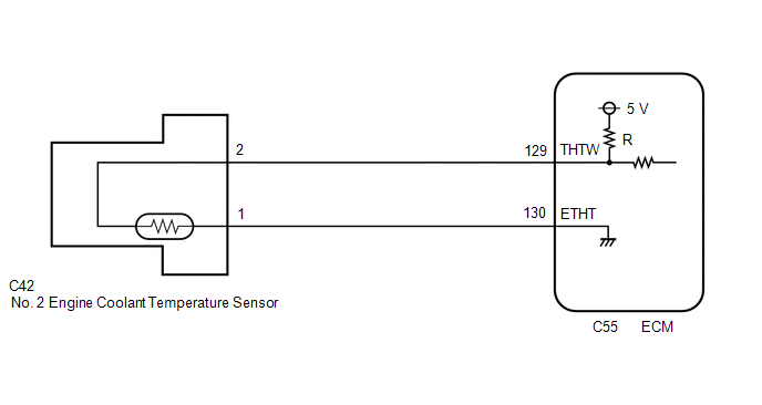
CAUTION / NOTICE / HINT

NOTICE:

  • Vehicle Control History may be stored in the hybrid vehicle control ECU assembly if the engine is malfunctioning. Certain vehicle condition information is recorded when Vehicle Control History is stored. Reading the vehicle conditions recorded in both the Freeze Frame Data and Vehicle Control History can be useful for troubleshooting.

    Click here

    (Select Powertrain in Health Check and then check the time stamp data.)

    Click here

  • If any "Engine Malfunction" Vehicle Control History item has been stored in the hybrid vehicle control ECU assembly, make sure to clear it. However, as all Vehicle Control History items are cleared simultaneously, if any Vehicle Control History items other than "Engine Malfunction" are stored, make sure to perform any troubleshooting for them before clearing Vehicle Control History.

    Click here

HINT:

Read Freeze Frame Data using the Techstream. The ECM records vehicle and driving condition information as Freeze Frame Data the moment a DTC is stored. When troubleshooting, Freeze Frame Data can help determine if the vehicle was moving or stationary, if the engine was warmed up or not, if the air fuel ratio was lean or rich, and other data from the time the malfunction occurred.

PROCEDURE

1.

INSPECT NO. 2 ENGINE COOLANT TEMPERATURE SENSOR

(a) Inspect the No. 2 engine coolant temperature sensor.

Click here

NG

REPLACE NO. 2 ENGINE COOLANT TEMPERATURE SENSOR

OK

2.

CHECK HARNESS AND CONNECTOR (NO. 2 ENGINE COOLANT TEMPERATURE SENSOR - ECM)

(a) Disconnect the No. 2 engine coolant temperature sensor connector.

(b) Disconnect the ECM connector.

(c) Measure the resistance according to the value(s) in the table below.

Standard Resistance:

Tester Connection

Condition

Specified Condition

C42-2 or C55-129 (THTW) - Body ground and other terminals

Always

10 kΩ or higher

OK

REPLACE ECM

NG

REPAIR OR REPLACE HARNESS OR CONNECTOR

    MIL Circuit

    Radiator Coolant Temperature Sensor Circuit Short to Battery or Open (P00B115)

    See More:

    Toyota Avalon (XX50) 2019-2022 Service & Repair Manual > Safety Connect System(for Gasoline Model): How To Proceed With Troubleshooting
    CAUTION / NOTICE / HINT HINT: Use the following procedure to troubleshoot the safety connect system. *: Use the Techstream. PROCEDURE 1. VEHICLE BROUGHT TO WORKSHOP NEXT 2. CUSTOMER PROBLEM ANALYSIS CHECK AND SYMPTOM CHECK HINT: In troubleshooting, confirm that the problem symptoms have been accurat ...

    Toyota Avalon (XX50) 2019-2022 Owners Manual

    Toyota Avalon (XX50) 2019-2022 Service & Repair Manual

    © 2024 Copyright www.tavalon.net
    0.0184