DESCRIPTION The engine has an ECM internal temperature sensor and intake air temperature sensor.
The
resistance of a thermistor within the ECM internal temperature sensor
and intake air temperature sensor increases as the temperature decreases
and decreases as the temperature increases. The voltage monitored by the ECM changes in accordance with the change in the resistance of the thermistor.
The ECM performs control based on these voltages. |
DTC No. | Detection Item |
DTC Detection Condition | Trouble Area |
MIL | Memory |
Note | | P111C62 |
Control Module Internal Temperature Sensor/Intake Air Temperature Sensor Signal Compare Failure |
All of the following conditions are met (2 trip detection logic):
- The auxiliary battery voltage is 8 V or higher.
- 7 hours or more have elapsed since the engine stopped on the previous trip.
- 0.5 seconds or more after power switch is turned to on (IG).
- Either of the following conditions is met:
- The minimum ECM internal temperature is -10°C (14°F) or higher.
- The minimum intake air temperature is -10°C (14°F) or higher.
- The difference between the readings of the ECM internal temperature and intake air temperature is higher than 20°C (36°F).
|
- Intake air temperature sensor (mass air flow meter sub-assembly)
- ECM (ECM internal temperature sensor)
| Comes on |
DTC stored | SAE Code: P111C | Related Data List |
DTC No. | Data List | |
P111C62 | Intake Air Temperature | |
Ambient Temperature |
HINT:
- Waiting is required to prevent the temperature of the engine from
affecting the readings. If the engine has been operated recently, it is
not possible to accurately compare the readings.
- For diagnosis, in order to duplicate the detection conditions of the
DTC, it is necessary to park the vehicle for 7 hours. Parking the
vehicle for 7 hours ensures that the actual temperature of the ECM
internal temperature and intake air temperature (for mass airflow meter
sub-assembly) are very similar. When the vehicle has been parked for
less than 7 hours, differences in the readings may exist, but this does
not necessarily indicate a fault.
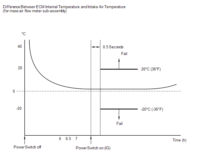
MONITOR DESCRIPTION 6,
6.5 and 7 hours after the engine has stopped, the ECM monitors the
voltage of the ECM internal temperature sensor and intake air
temperature sensor. If the difference between
the readings of the ECM internal temperature and intake air temperature
is more than 20°C (36°F), the ECM determines that there is a malfunction
in the ECM internal temperature sensor circuit or intake air
temperature sensor circuit and stores a DTC and illuminates the MIL. MONITOR STRATEGY |
Related DTCs | P111C: Intake air temperature / engine control module internal temperature sensor correlation | |
Required Sensors/Components (Main) | Intake air temperature sensor
Engine control module internal temperature sensor | |
Required Sensors/Components (Related) |
- | | Frequency of Operation |
Once per driving cycle | | Duration |
- | | MIL Operation |
2 driving cycles | | Sequence of Operation |
None | TYPICAL ENABLING CONDITIONS |
All of the following conditions are met |
- | | Power switch |
Off | | Engine |
Stall | | Soak time |
6, 6.5 and 7 hours | |
Time after ECM power on |
0.5 seconds or more | | One of the following conditions is met |
(a) or (b) | | (a) Engine control module internal temperature |
-10°C (14°F) or higher | |
(b) Intake air temperature |
-10°C (14°F) or higher | |
Engine control module internal temperature sensor circuit fail (P06AD, P06AE) |
Not detected | |
Intake air temperature sensor circuit fail (P0112, P0113) |
Not detected | |
Soak timer fail (P2610) |
Not detected | |
Auxiliary battery voltage |
8 V or higher | TYPICAL MALFUNCTION THRESHOLDS |
Deviated engine control module internal temperature and intake air temperature |
Less than -20°C (-36°F), or higher than 20°C (36°F) | CONFIRMATION DRIVING PATTERN
HINT:
- After repair has been completed, clear the DTC and then check that the
vehicle has returned to normal by performing the following All Readiness
check procedure.
Click here 
- When clearing the permanent DTCs, refer to the "CLEAR PERMANENT DTC" procedure.
Click here
- Connect the Techstream to the DLC3.
- Turn the power switch on (IG).
- Turn the Techstream on.
- Clear the DTCs (even if no DTCs are stored, perform the clear DTC procedure).
- Turn the power switch off.
- With the engine stopped, leave the vehicle as is for 7.5 hours or more [A].
- Turn the power switch on (IG).
- Turn the Techstream on.
- Wait 1 seconds [B].
- Enter the following menus: Powertrain / Engine / Trouble Codes [C].
- Read the pending DTCs.
HINT:
- If a pending DTC is output, the system is malfunctioning.
- If a pending DTC is not output, perform the following procedure.
- Enter the following menus: Powertrain / Engine / Utility / All Readiness.
- Input the DTC: P111C62.
- Check the DTC judgment result.
|
Techstream Display |
Description |
|
NORMAL |
- DTC judgment completed
- System normal
|
|
ABNORMAL |
- DTC judgment completed
- System abnormal
|
|
INCOMPLETE |
- DTC judgment not completed
- Perform driving pattern after confirming DTC enabling conditions
|
HINT:
CAUTION / NOTICE / HINT
NOTICE:
HINT: Read
Freeze Frame Data using the Techstream. The ECM records vehicle and
driving condition information as Freeze Frame Data the moment a DTC is
stored. When troubleshooting, Freeze Frame Data can help determine if
the vehicle was moving or stationary, if the engine was warmed up or
not, if the air fuel ratio was lean or rich, and other data from the
time the malfunction occurred. PROCEDURE
| 1. |
CHECK ANY OTHER DTCS OUTPUT (IN ADDITION TO DTC P111C62) |
(a) Connect the Techstream to the DLC3. (b) Turn the power switch on (IG).
(c) Turn the Techstream on. (d) Enter the following menus: Powertrain / Engine / Trouble Codes.
(e) Read the DTCs and record the Freeze Frame Data. Powertrain > Engine > Trouble Codes
|
Result | Proceed to | |
DTC P111C62 is output |
A | | DTC P111C62 and other DTCs are output |
B | HINT: If any DTCs other than P111C62 are output, troubleshoot those DTCs first.
| B |
 | GO TO DTC CHART |
|
A |
 | |
| 2. |
CHECK FREEZE FRAME DATA (INTAKE AIR TEMPERATURE AND AMBIENT TEMPERATURE) |
(a) Connect the Techstream to the DLC3. (b) Turn the power switch on (IG).
(c) Turn the Techstream on. (d) Using the Techstream, read the values displayed in the Freeze Frame Data recorded in step 1. Powertrain > Engine > DTC(P111C62) > Freeze Frame Data
|
Tester Display | | Intake Air Temperature | |
Ambient Temperature | (e) Read the value displayed on the Techstream.
Standard: Difference between the Intake Air Temperature and the Ambient Temperature is within 15°C (27°F).
HINT:
- When the engine is cold, the value of the intake air temperature, ECM
internal temperature and ambient temperature should be approximately the
same.
- Perform "Inspection After Repair" after replacing the mass air flow meter sub-assembly.
Click here
| OK |
| REPLACE ECM |
| NG |
| REPLACE MASS AIR FLOW METER SUB-ASSEMBLY | |


