DESCRIPTION Refer to DTC P001001. Click here
 |
DTC No. | Detection Item |
DTC Detection Condition | Trouble Area |
MIL | Memory |
Note | | P001200 |
Camshaft Position "A" - Timing Over-Retarded Bank 1 |
With
engine warmed up and while driving in urban area (engine speed 4000 rpm
or less), intake side valve timing does not change in retarded
position, and target and actual valve timing do not match (1 trip
detection logic). |
- Camshaft timing gear assembly
- Cam timing control motor with EDU assembly
- ECM
| Comes on |
DTC stored | SAE Code: P0012 | MONITOR DESCRIPTION
This
DTC is output when a valve timing stuck condition is detected. With the
engine speed at 4000 rpm or less in the retard angle position, if the
valve timing does not vary, and there is a large difference in the
target and actual valve timing, it is determined that a malfunction has
occurred. When this malfunction is detected, the ECM will illuminate the
MIL and store this DTC. MONITOR STRATEGY |
Related DTCs | P0012: Retarded camshaft timing | |
Required Sensors/Components (Main) | Camshaft timing gear assembly
Cam timing control motor with EDU assembly | |
Required Sensors/Components (Related) |
Crankshaft position sensor Camshaft position sensor Engine coolant temperature sensor | |
Frequency of Operation | Continuous | |
Duration | Less than 10 seconds | |
MIL Operation | Immediate | |
Sequence of Operation | None | TYPICAL ENABLING CONDITIONS |
Monitor runs whenever the following DTCs are not stored |
P0010, P1360, P1362, P1364, P1366, P2614 (Motor drive VVT system control module)
P0016 (VVT system - misalignment) P0101, P0102, P0103 (Mass air flow meter)
P0107, P0108 (Manifold absolute pressure) P0117, P0118 (Engine coolant temperature sensor)
P0125 (Insufficient engine coolant temperature for closed loop fuel control)
P0335, P0337, P0338 (Crankshaft position sensor) P0340, P0342, P0343 (Camshaft position sensor)
P0365, P0367, P0368 (Exhaust camshaft position sensor) | |
Auxiliary battery voltage | 11 V or higher | |
Engine speed | 500 to 4000 rpm | |
Engine coolant temperature | 75 to 120°C (167 to 248°F) | TYPICAL MALFUNCTION THRESHOLDS |
Both of the following conditions are met |
- | | Deviation of actual valve timing and target valve timing |
More than 5°CA (Crankshaft Angle) for 5 seconds or more | |
Valve timing | No change at retarded valve timing | MONITOR RESULT
Refer to detailed information in Checking Monitor Status. Click here
P0012: Exhaust Gas Recirculation/VVT / IN VVT STUCK B1 |
Monitor ID | Test ID |
Scaling | Unit |
Description | | $35 |
$81 | Multiply by 0.01 |
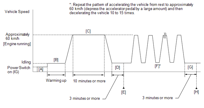
Second | Forced movement of cam timing control motor time | CONFIRMATION DRIVING PATTERN
HINT:
- After repair has been completed, clear the DTC and then check that the
vehicle has returned to normal by performing the following All Readiness
check procedure.
Click here
- When clearing the permanent DTCs, refer to the "CLEAR PERMANENT DTC" procedure.
Click here
- Connect the Techstream to the DLC3.
- Turn the power switch on (IG).
- Turn the Techstream on.
- Clear the DTCs (even if no DTCs are stored, perform the clear DTC procedure).
- Turn the power switch off and wait for at least 30 seconds.
- Turn the power switch on (IG) [A].
- Turn the Techstream on.
- Put the engine in Inspection Mode (Maintenance Mode).
Click here
- Start the engine and warm it up until the engine coolant temperature reaches 75°C (167°F) or higher [B].
- With the engine running, drive the vehicle at approximately 60 km/h (37 mph) for 10 minutes or more [C].
CAUTION:
When performing the confirmation driving pattern, obey all speed limits and traffic laws.
HINT:
If the engine stops, further depress the accelerator pedal to restart the engine.
- Idle the engine for 3 minutes or more [D].
- Enter the following menus: Powertrain / Engine / Trouble Codes [E].
- Read the pending DTCs.
HINT:
- If a pending DTC is output, the system is malfunctioning.
- If a pending DTC is not output, perform the following procedure.
- Enter the following menus: Powertrain / Engine / Utility / All Readiness.
- Input the DTC: P001200.
- Check the DTC judgment result.
|
Techstream Display |
Description |
|
NORMAL |
- DTC judgment completed
- System normal
|
|
ABNORMAL |
- DTC judgment completed
- System abnormal
|
|
INCOMPLETE |
- DTC judgment not completed
- Perform driving pattern after confirming DTC enabling conditions
|
HINT:
- With the engine running, repeat the pattern of accelerating the vehicle
from rest to approximately 60 km/h (37 mph) and then decelerating the
vehicle 10 to 15 times [F].
CAUTION:
When performing the confirmation driving pattern, obey all speed limits and traffic laws.
HINT:
- If the engine stops, further depress the accelerator pedal to restart the engine.
- Depress the accelerator pedal by a large amount.
- Idle the engine for 3 minutes or more [G].
- Enter the following menus: Powertrain / Engine / Trouble Codes [H].
- Read the pending DTCs.
HINT:
- If a pending DTC is output, the system is malfunctioning.
- If a pending DTC is not output, perform the following procedure.
- Check the DTC judgment result again.
HINT:
CAUTION / NOTICE / HINT
NOTICE:
HINT:
PROCEDURE |
1. | CHECK ANY OTHER DTCS OUTPUT (IN ADDITION TO DTC P001200) |
(a) Connect the Techstream to the DLC3. (b) Turn the power switch on (IG).
(c) Turn the Techstream on. (d) Enter the following menus: Powertrain / Engine / Trouble Codes.
(e) Read the DTCs. Powertrain > Engine > Trouble Codes
|
Result | Proceed to | |
DTC P001200 is output |
A | | DTC P001200 and other DTCs are output |
B | HINT: If any DTCs other than P001200 are output, troubleshoot those DTCs first.
| B |
 | GO TO DTC CHART |
|
A |
 | |
| 2. |
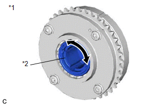
INSPECT CAMSHAFT TIMING GEAR ASSEMBLY |
|
*1 | Camshaft Timing Gear Assembly | |
*2 | Eccentric Shaft |
(a) Remove the cam timing control motor with EDU assembly. Click here
(b) Check if the eccentric shaft of the camshaft timing gear assembly rotates smoothly.
NOTICE: If the camshaft is at a position where a valve is about to open, the eccentric shaft may become difficult to rotate.
OK: Rotates smoothly. HINT: Perform
"Inspection After Repair" after replacing the camshaft timing gear
assembly, or removing the cam timing control motor with EDU assembly. Click here
| NG | |
REPLACE CAMSHAFT TIMING GEAR ASSEMBLY |
|
OK | |
| |
| 3. |
REPLACE CAM TIMING CONTROL MOTOR WITH EDU ASSEMBLY |
(a) Replace the cam timing control motor with EDU assembly. Click here
HINT: Perform "Inspection After Repair" after replacing the cam timing control motor with EDU assembly.
Click here
|
NEXT | |
| |
(a) Connect the Techstream to the DLC3.
(b) Turn the power switch on (IG). (c) Turn the Techstream on. (d) Clear the DTCs. Powertrain > Engine > Clear DTCs
(e) Turn the power switch off and wait for at least 30 seconds.
|
NEXT | |
| |
| 5. |
CONFIRM WHETHER MALFUNCTION HAS BEEN SUCCESSFULLY REPAIRED |
(a) Drive the vehicle in accordance with the driving pattern described in Confirmation Driving Pattern.
(b) Enter the following menus: Powertrain / Engine / Trouble Codes. (c) Read the DTCs. Powertrain > Engine > Trouble Codes
|
Result | Proceed to | |
DTCs are not output | A | |
DTC P001200 is output |
B |
| A |
| END |
| B |
| REPLACE ECM | |


