DESCRIPTION
 Variable
oil pump control uses the oil pressure control valve assembly, engine
oil temperature sensor, oil pressure sensor and ECM to optimize the oil
pressure and oil volume required by each component to reduce friction by
monitoring the engine temperature and engine speed. The oil pressure
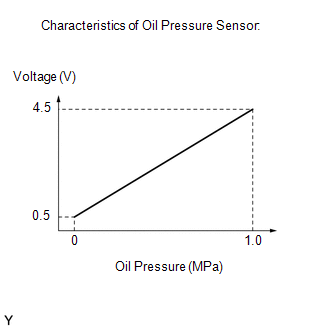
sensor utilizes a semiconductor type pressure sensor that changes
resistance in accordance with changes in pressure. An internal
electrical signal that varies with the change in resistance is amplified
and sent to the ECM as the engine oil pressure signal. |
DTC No. | Detection Item |
DTC Detection Condition | Trouble Area |
MIL | Memory |
Note | | P052012 |
Engine Oil Pressure Sensor/Switch "A" Circuit Short to Battery |
The oil pressure sensor output voltage is higher than 4.78 V for 5 seconds or more (1 trip detection logic). |
- Open or short in oil pressure sensor (oil pressure sender gauge assembly) circuit
- Oil pressure sensor (oil pressure sender gauge assembly)
- ECM
| Comes on |
DTC stored | SAE Code: P0523 | |
P052014 | Engine Oil Pressure Sensor/Switch "A" Circuit Short to Ground or Open |
The oil pressure sensor output voltage is less than 0.23 V for 5 seconds or more (1 trip detection logic). |
- Open or short in oil pressure sensor (oil pressure sender gauge assembly) circuit
- Oil pressure sensor (oil pressure sender gauge assembly)
- ECM
| Comes on |
DTC stored | SAE Code: P0522 | Related Data List |
DTC No. | Data List | |
P052012 | Engine Oil Pressure | |
P052014 | MONITOR DESCRIPTION
The
ECM calculates the engine oil pressure based on the output voltage of
the oil pressure sensor (oil pressure sender gauge assembly). If the
signal output from the oil pressure sensor is outside of the specified
range, the MIL is illuminated and a DTC is stored. MONITOR STRATEGY |
Related DTCs | P0522: Engine oil pressure sensor range check (low voltage)
P0523: Engine oil pressure sensor range check (high voltage) | |
Required Sensors/Components (Main) | Oil pressure sensor (oil pressure sender gauge assembly) | |
Required Sensors/Components (Related) |
- | | Frequency of Operation |
Continuous | | Duration |
5 seconds | | MIL Operation |
Immediate | | Sequence of Operation |
None | TYPICAL ENABLING CONDITIONS |
Monitor runs whenever the following DTCs are not stored |
None | | Both of the following conditions are met |
- | | Auxiliary battery voltage |
8 V or higher | | Power switch |
On (IG) | TYPICAL MALFUNCTION THRESHOLDS P0522: Range Check (Low Voltage) |
Engine oil pressure sensor voltage | Less than 0.23 V | P0523: Range Check (High Voltage) |
Engine oil pressure sensor voltage | Higher than 4.78 V | CONFIRMATION DRIVING PATTERN
HINT:
- After repair has been completed, clear the DTC and then check that the
vehicle has returned to normal by performing the following All Readiness
check procedure.
Click here 
- When clearing the permanent DTCs, refer to the "CLEAR PERMANENT DTC" procedure.
Click here
- Connect the Techstream to the DLC3.
- Turn the power switch on (IG).
- Turn the Techstream on.
- Clear the DTCs (even if no DTCs are stored, perform the clear DTC procedure).
- Turn the power switch off and wait for at least 30 seconds.
- Turn the power switch on (IG) [A].
- Turn the Techstream on.
- Wait 10 seconds or more [B].
- Enter the following menus: Powertrain / Engine / Trouble Codes [C].
- Read the pending DTCs.
HINT:
- If a pending DTC is output, the system is malfunctioning.
- If a pending DTC is not output, perform the following procedure.
- Enter the following menus: Powertrain / Engine / Utility / All Readiness.
- Input the DTC: P052012 or P052014.
- Check the DTC judgment result.
|
Techstream Display |
Description |
|
NORMAL |
- DTC judgment completed
- System normal
|
|
ABNORMAL |
- DTC judgment completed
- System abnormal
|
|
INCOMPLETE |
- DTC judgment not completed
- Perform driving pattern after confirming DTC enabling conditions
|
HINT:
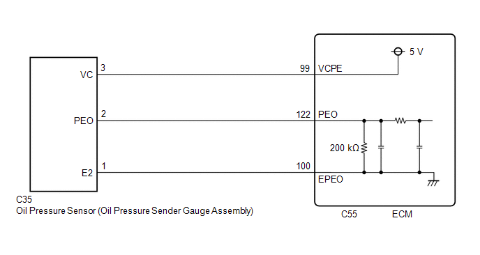
WIRING DIAGRAM
 CAUTION / NOTICE / HINT
NOTICE:
HINT: Read
Freeze Frame Data using the Techstream. The ECM records vehicle and
driving condition information as Freeze Frame Data the moment a DTC is
stored. When troubleshooting, Freeze Frame Data can help determine if
the vehicle was moving or stationary, if the engine was warmed up or
not, if the air fuel ratio was lean or rich, and other data from the
time the malfunction occurred. PROCEDURE
| 1. |
CHECK HARNESS AND CONNECTOR |
|
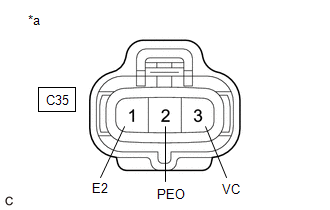
*a | Front view of wire harness connector
(to Oil Pressure Sensor (Oil Pressure Sender Gauge Assembly)) |
HINT: Make sure that the connector is properly connected. If it is not, securely connect it and check for DTCs again.
(a) Disconnect the oil pressure sensor (oil pressure sender gauge assembly) connector.
(b) Turn the power switch on (IG). (c) Measure the voltage according to the value(s) in the table below.
Standard Voltage: |
Tester Connection | Condition |
Specified Condition | |
C35-3 (VC) - Body ground |
Power switch on (IG) |
4.5 to 5.5 V | |
C35-2 (PEO) - Body ground |
Power switch on (IG) |
Below 0.1 V | (d) Turn the power switch off and wait for at least 30 seconds.
(e) Measure the resistance according to the value(s) in the table below.
Standard Resistance: |
Tester Connection | Condition |
Specified Condition | |
C35-2 (PEO) - C35-1 (E2) |
Power switch off | 190 to 210 kΩ | |
C35-1 (E2) - Body ground |
Always | Below 1 Ω |
| OK |
 | REPLACE OIL PRESSURE SENSOR (OIL PRESSURE SENDER GAUGE ASSEMBLY) |
|
NG |
 | |
| 2. |
CHECK HARNESS AND CONNECTOR (OIL PRESSURE SENSOR (OIL PRESSURE SENDER GAUGE ASSEMBLY) - ECM) |
(a) Disconnect the oil pressure sensor (oil pressure sender gauge assembly) connector.
(b) Disconnect the ECM connector. (c) Measure the resistance according to the value(s) in the table below.
Standard Resistance: |
Tester Connection | Condition |
Specified Condition | |
C35-1 (E2) - C55-100 (EPEO) |
Always | Below 1 Ω | |
C35-2 (PEO) - C55-122 (PEO) |
Always | Below 1 Ω | |
C35-3 (VC) - C55-99 (VCPE) |
Always | Below 1 Ω | |
C35-2 (PEO) or C55-122 (PEO) - Body ground and other terminals |
Always | 10 kΩ or higher | |
C35-3 (VC) or C55-99 (VCPE) - Body ground and other terminals |
Always | 10 kΩ or higher |
| OK |
| REPLACE ECM |
| NG |
| REPAIR OR REPLACE HARNESS OR CONNECTOR | | 

