DESCRIPTION These DTCs are stored when a malfunction occurs in the navigation antenna assembly. |
DTC No. | Detection Item |
DTC Detection Condition | Trouble Area | |
B15C0 | GPS Antenna Connection Malfunction(short) |
Navigation antenna malfunction |
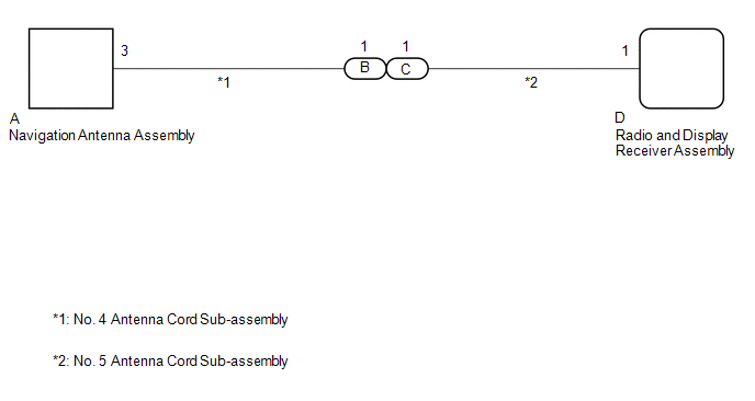
- Navigation antenna assembly
- No. 4 antenna cord sub-assembly
- No. 5 antenna cord sub-assembly
- Radio and display receiver assembly
| | B15C1 |
GPS Antenna Connection Malfunction(break) |
Navigation antenna power source malfunction |
- Navigation antenna assembly
- No. 4 antenna cord sub-assembly
- No. 5 antenna cord sub-assembly
- Radio and display receiver assembly
| WIRING DIAGRAM
 CAUTION / NOTICE / HINT
NOTICE:
- Depending on the parts that are replaced during vehicle inspection or
maintenance, performing initialization, registration or calibration may
be needed. Refer to Precaution for Audio and Visual System.
Click here 
- When replacing the radio and display receiver assembly, always replace
it with a new one. If a radio and display receiver assembly which was
installed to another vehicle is used, the following may occur:
- A communication malfunction DTC may be stored.
- The radio and display receiver assembly may not operate normally.
- Check that the No. 4 antenna cord sub-assembly and No. 5 antenna cord
sub-assembly is properly installed and does not have any sharp bends,
pinching or loose connections before performing following procedure.
Click here
PROCEDURE (a) Clear the DTCs. Body Electrical > Navigation System > Clear DTCs
(b) Recheck for DTCs and check that no DTCs are output. Body Electrical > Navigation System > Trouble Codes
OK: No DTCs are output.
| OK |  |
USE SIMULATION METHOD TO CHECK |
|
NG |
 | |
| 2. |
INSPECT NO. 5 ANTENNA CORD SUB-ASSEMBLY |
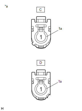
(a) Remove the No. 5 antenna cord sub-assembly. Click here
| (b) Measure the resistance according to the value(s) in the table below.
Standard Resistance: |
Tester Connection | Condition |
Specified Condition | |
C-1 - D-1 | Always |
Below 1 Ω | |
C-1a - D-1a | Always |
Below 1 Ω | |
C-1 or D-1 - Body ground |
Always | 10 kΩ or higher | |
 |
|
*a | Component without harness connected
(No. 5 Antenna Cord Sub-assembly) | | |
| NG |
| REPLACE NO. 5 ANTENNA CORD SUB-ASSEMBLY |
|
OK | |
| |
| 3. |
INSPECT NO. 4 ANTENNA CORD SUB-ASSEMBLY |
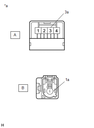
(a) Remove the No. 4 antenna cord sub-assembly. Click here
| (b) Measure the resistance according to the value(s) in the table below.
Standard Resistance: |
Tester Connection | Condition |
Specified Condition | |
A-3 - B-1 | Always |
Below 1 Ω | |
A-3a - B-1a | Always |
Below 1 Ω | |
A-3 or B-1 - Body ground |
Always | 10 kΩ or higher | |
 |
|
*a | Component without harness connected
(No. 4 Antenna Cord Sub-assembly) | | |
| NG |
| REPLACE NO. 4 ANTENNA CORD SUB-ASSEMBLY |
|
OK | |
| |
| 4. |
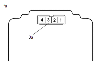
INSPECT NAVIGATION ANTENNA ASSEMBLY | (a) Remove the navigation antenna assembly.
Click here
| (b) Measure the resistance according to the value(s) in the table below.
Standard Resistance: |
Tester Connection | Condition |
Specified Condition | |
3 - 3a | Always |
50 to 500 Ω | |
 |
|
*a | Component without harness connected
(Navigation Antenna Assembly) | | |
| OK |
| REPLACE RADIO AND DISPLAY RECEIVER ASSEMBLY |
| NG |
| REPLACE NAVIGATION ANTENNA ASSEMBLY | |


