REMOVAL CAUTION / NOTICE / HINT
The
necessary procedures (adjustment, calibration, initialization or
registration) that must be performed after parts are removed and
installed, or replaced during HV battery removal/installation are shown
below. Necessary Procedures After Parts Removed/Installed/Replaced |
Replaced Part or Performed Procedure |
Necessary Procedure | Effect/Inoperative Function when Necessary Procedure not Performed |
Link | |
*: When performing learning using the Techstream.
Click here  | |
Auxiliary battery terminal is disconnected/reconnected |
Perform steering sensor zero point calibration |
Lane departure alert system (w/ Steering Control) |
| |
Pre-collision system | | Intelligent clearance sonar system* | |
Lighting System (for HV Model with Cornering Light) | |
Memorize steering angle neutral point |
Parking assist monitor system |
| |
Panoramic view monitor system |
| |
Replacement of HV battery | Battery status info update |
HV battery status information cannot be updated |
| |
Replacement of hybrid battery terminal block |
High voltage fuse accumulated load history reset |
DTCs are stored |
CAUTION:
NOTICE:
- After turning the power switch off, waiting time may be required before
disconnecting the cable from the negative (-) auxiliary battery
terminal. Therefore, make sure to read the disconnecting the cable from
the negative (-) auxiliary battery terminal notices before proceeding
with work.
Click here
- When the cable is disconnected from the negative (-) auxiliary battery
terminal, some systems need to be initialized after the cable is
reconnected.
Click here
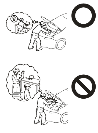
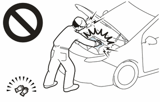
- If the HV battery has been struck or dropped, replace it.
- When connecting a connector to the HV battery, confirm that the connector is securely connected through the following:
- Push the connector until a click sound is heard.
- Visually check and confirm that the connector is securely connected by pulling on it.
- Make sure to insulate the high-voltage connectors and terminals of the HV battery with insulating tape after removing it.
If the HV battery stored without insulating the connectors and terminals, electric shock or fire may result.
- When performing repairs around the HV battery, such as using a tap, do not allow metal shavings to enter the HV battery.
- Do not touch any high voltage wire harnesses, connectors or parts with bare hands.
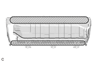
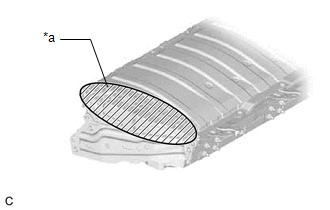
- Hold the areas shown in the illustration and lift the HV battery.
- Do not allow foreign matter, such as grease or oil, to adhere to the bolts or nuts of the HV battery.
- Do not put your hands into the openings of the HV battery.
- When removing/installing/moving the HV battery, make sure not to tilt it more than 80°.
- Do not climb on top of or stand on the HV battery.
- Do not allow any foreign matter or water to enter the HV battery.
- If any bolts, nuts or clips are dropped into the HV battery, make sure to remove them.
HINT: When
disposing of an HV battery, make sure to return it through an authorized
collection agent who is capable of handling it safely. If the HV
battery is returned via the manufacturer specified route, it will be
returned properly and in a safe manner by an authorized collection
agent. PROCEDURE 1. REMOVE SERVICE PLUG GRIP
Click here 2. DISCONNECT ENGINE ROOM MAIN WIRE
Click here 3. REMOVE CONNECTOR COVER ASSEMBLY
Click here 4. CHECK TERMINAL VOLTAGE
Click here 5. INSTALL CONNECTOR COVER ASSEMBLY
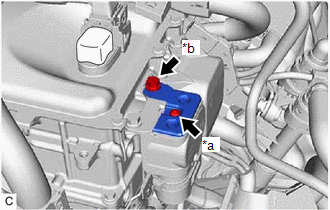
CAUTION: Be sure to wear insulated gloves.
| (a)
Using a T25 "TORX" socket wrench, install the connector cover assembly
to the inverter with converter assembly with the bolt (A). Torque:
4.5 N·m {46 kgf·cm, 40 in·lbf} NOTICE: Do not touch the waterproof seal of the connector cover assembly. |
|
(b) Install the bolt (B). Torque: 8.0 N·m {82 kgf·cm, 71 in·lbf}
6. CONNECT ENGINE ROOM MAIN WIRE Click here
7. REMOVE BATTERY COOLING BLOWER ASSEMBLY
Click here 8. REMOVE NO. 1 HV BATTERY COVER PANEL RH
CAUTION: Be sure to wear insulated gloves.
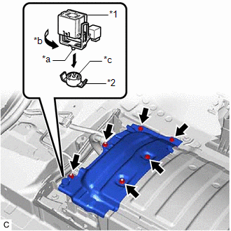
| (a) Using the service plug grip, remove the battery cover lock striker.
HINT: Insert
the projection of the service plug grip and turn the button of the
battery cover lock striker counterclockwise to release the lock. |
 |
|
*1 | Service Plug Grip | |
*2 | Battery Cover Lock Striker | |
*a | Projection | |
*b | Turn | |
*c | Button | | |
(b) Remove the 3 bolts, 3 nuts and No. 1 HV battery cover panel RH from the HV battery.
9. DISCONNECT HV FLOOR UNDER WIRE CAUTION: Be sure to wear insulated gloves.
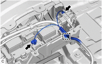
| (a) Disconnect the 2 HV battery junction block assembly connectors.
NOTICE: Insulate
each disconnected high-voltage connector with insulating tape. Wrap the
connector from the wire harness side to the end of the connector. |
|
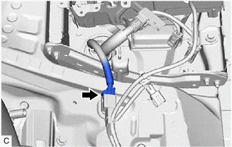
(b) Disconnect the shield ground from the HV battery.
| (c) Disconnect the floor wire connector. | |
10. DISCONNECT FLOOR WIRE CAUTION: Be sure to wear insulated gloves.
(b) Disconnect the electric vehicle battery plug assembly connector. (c) Disconnect the HV battery junction block assembly connector.
11. REMOVE NO. 1 INDOOR ELECTRICAL KEY ANTENNA ASSEMBLY Click here
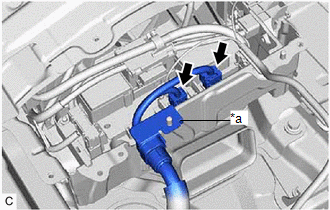
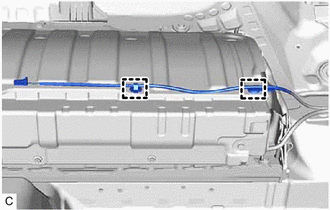
12. DISCONNECT FLOOR WIRE CAUTION:
Be sure to wear insulated gloves.
| (a) Disengage the 2 clamps to disconnect the floor wire. |
|
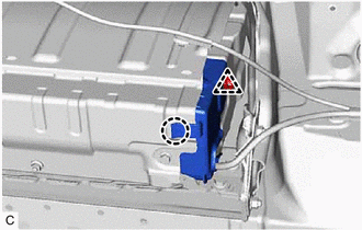
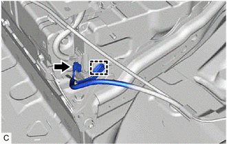
13. REMOVE NO. 1 HYBRID BATTERY EXHAUST DUCT CAUTION: Be sure to wear insulated gloves.
(b) Disengage the claw to remove the No. 1 hybrid battery exhaust duct from the HV battery.
14. DISCONNECT FLOOR WIRE CAUTION: Be sure to wear insulated gloves.
(b) Disconnect the battery voltage sensor connector. 15. REMOVE HV BATTERY
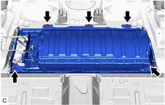
CAUTION: Be sure to wear insulated gloves.
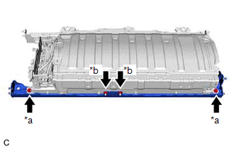
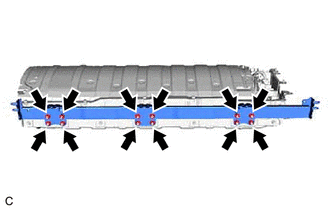
| (a) Remove the 5 bolts and HV battery from the vehicle body.
NOTICE:
- Do not allow foreign matter, such as grease or oil, to adhere to the bolts of the HV battery.
- To prevent the wire harness from being caught, make sure to bundle the wire harness using insulating tape or equivalent.
- Use cardboard or another similar material to protect the HV battery and vehicle body from damage.
- Since the HV battery is very heavy, 2 people are needed to remove it.
When removing the HV battery, be careful not to damage the parts around
it.
- When removing the HV battery from the vehicle, do not allow it to contact the vehicle.
- When removing/installing/moving the HV battery, make sure not to tilt it more than 80°.
- Insulate the disconnected terminals or connectors with insulating tape.
- If the HV battery has been struck or dropped, replace it.
| |
16. REMOVE NO. 4 HV BATTERY SHIELD SUB-ASSEMBLY CAUTION: Be sure to wear insulated gloves.
| (a) Remove the 4 nuts and No. 4 HV battery shield sub-assembly from the HV battery. |
|
17. REMOVE NO. 3 HV BATTERY SHIELD SUB-ASSEMBLY CAUTION: Be sure to wear insulated gloves.
| (a) Remove the 4 nuts and No. 3 HV battery shield sub-assembly from the HV battery. |
|
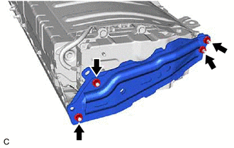
18. REMOVE NO. 4 HV BATTERY END PLATE SUB-ASSEMBLY CAUTION: Be sure to wear insulated gloves.
| (a) Remove the 2 bolts, 2 nuts and No. 4 HV battery end plate sub-assembly from the HV battery. |
|
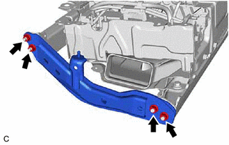
19. REMOVE NO. 5 HV BATTERY END PLATE SUB-ASSEMBLY CAUTION: Be sure to wear insulated gloves.
| (a) Remove the 12 nuts and No. 5 HV battery end plate sub-assembly from the HV battery. |
|
20. REMOVE UPPER HV BATTERY COVER SUB-ASSEMBLY Click here
21. REMOVE NO. 1 HV BATTERY SHIELD PANEL
Click here 22. REMOVE BATTERY VOLTAGE SENSOR
Click here 23. REMOVE HYBRID BATTERY TERMINAL BLOCK
Click here 24. REMOVE HV BATTERY JUNCTION BLOCK ASSEMBLY
Click here 25. REMOVE NO. 2 HYBRID BATTERY SHIELD SUB-ASSEMBLY
Click here 26. REMOVE NO. 1 HV BATTERY INTAKE DUCT LH
Click here |