Toyota Avalon (XX50) 2019-2022 Service & Repair Manual: Drive Start Control

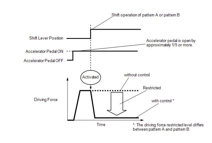
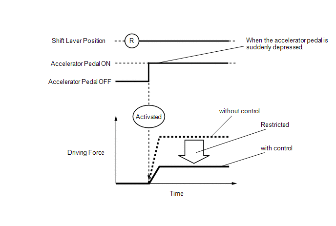
DESCRIPTION

The drive start control is controlled by the hybrid vehicle control ECU.

If the hybrid vehicle control ECU determines that the shift lever and accelerator pedal are operated abnormally, driving force is restricted and, when necessary, a warning is displayed on the combination meter assembly.

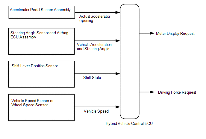
CAUTION / NOTICE / HINT

HINT:

Even if the accelerator pedal position is maintained, the driving force may increase when driving uphill and decrease when driving downhill. This is due to drive start control controlling the driving force, and is not a malfunction.

PROCEDURE

1.

SYMPTOM CONFIRMATION

(a) Interview the customer to confirm the problem.

Result

Proceed to

Hunting

A

Hesitation/poor acceleration

B

B

GO TO STEP 8

A

2.

PAST ACTIVATION CONFIRMATION

(a) Check if the customer operated the vehicle in a way that would cause the drive start control to operate.

Drive Start Control Activation Conditions

Shift control
  • Activation conditions
  • Pattern A (When all of the following conditions are met, control starts.)
    • The accelerator pedal is open by approximately 1/5 or more.
    • The shift lever is moved from P to (D or S) or R.
  • Pattern B (When all of the following conditions are met, control starts.)
    • The accelerator pedal is open by approximately 1/5 or more.
    • The shift lever is moved from R to (D or S), from (D or S) or N to R.
  • Items Controlled
    • Driving force is restricted.
  • Deactivation Conditions
    • The accelerator pedal is released.
    • The shift lever is in P or N.
Reverse control
  • Activation conditions
  • The shift lever is in R.
  • The accelerator pedal is depressed excessively.
  • Items Controlled
    • Driving force is restricted.
  • Deactivation Conditions
    • The accelerator pedal is released.
    • The shift lever is moved to any position other than R.

HINT:

  • The driving force restricted level differs between Pattern A, Pattern B and Reverse control.
  • During Shift control or Reverse control, driving force is adjusted based on the road gradient and steering angle.
Result

Proceed to

Performed

A

Not performed

B

B

SYSTEM NORMAL (GO TO PROBLEM SYMPTOM TABLE)

A

3.

CHECK DTC OUTPUT (HEALTH CHECK)

(a) Connect the Techstream to the DLC3.

(b) Turn the power switch on (IG).

(c) Turn the Techstream on.

(d) Enter the following menus: System Select / Health Check.

(e) Check the DTCs.

(f) Turn the power switch off.

Result

Proceed to

DTCs are not output

A

DTC is output

B

B

GO TO DTC CHART

A

4.

READ VALUE USING TECHSTREAM (FR, FL, RR, RL WHEEL SPEED)

(a) Connect the Techstream to the DLC3.

(b) Turn the power switch on (READY).

(c) Turn the Techstream on.

(d) Enter the following menus: Chassis / ABS/VSC/TRAC / Data List / FR Wheel Speed, FL Wheel Speed, RR Wheel Speed and RL Wheel Speed.

Chassis > ABS/VSC/TRAC > Data List

Tester Display

FR Wheel Speed

FL Wheel Speed

RR Wheel Speed

RL Wheel Speed

(e) Read the values displayed on the Techstream.

Standard:

Condition

Specified Condition

Vehicle stopped

0 km/h (0 mph)

Vehicle being driven at constant speed between 16 to 64 km/h (10 to 40 mph)

No large fluctuations when driving at a constant speed

CAUTION:

When performing the confirmation driving pattern, obey all speed limits and traffic laws.

HINT:

Data can be captured relatively easily by using the snapshot function in the Data List. Confirm the data after performing the drive test.

(f) Turn the power switch off.

NG

INSPECT FRONT OR REAR SPEED SENSOR

OK

5.

READ VALUE USING TECHSTREAM (VEHICLE SPEED)

(a) Connect the Techstream to the DLC3.

(b) Turn the power switch on (READY).

(c) Turn the Techstream on.

(d) Enter the following menus: Powertrain / Hybrid Control / Data List / Vehicle Speed.

Powertrain > Hybrid Control > Data List

Tester Display

Vehicle Speed

(e) Read the value displayed on the Techstream.

Standard:

Inspection Condition

Specified Condition

Vehicle stopped

0 km/h (0 mph)

Vehicle being driven at a constant speed

(16 to 64 km/h (10 to 40 mph))

No large fluctuations in displayed speed

CAUTION:

Perform this road test only in an appropriate safe location, in accordance with all local laws.

HINT:

Data can be captured relatively easily by using the snapshot function in the Data List. Confirm the data after performing the drive test.

(f) Turn the power switch off.

NG

INSPECT ELECTRONICALLY CONTROLLED BRAKE SYSTEM (HOW TO PROCEED WITH TROUBLESHOOTING)

OK

6.

READ VALUE USING TECHSTREAM (DECELERATION SENSOR)

(a) Connect the Techstream to the DLC3.

(b) Turn the power switch on (READY).

(c) Turn the Techstream on.

(d) Enter the following menus: Chassis / ABS/VSC/TRAC / Data List / Deceleration Sensor, Deceleration Sensor2.

Chassis > ABS/VSC/TRAC > Data List

Tester Display

Deceleration Sensor

Deceleration Sensor2

(e) Read the values displayed on the Techstream.

Standard:

Condition

Specified Condition

During deceleration

Values change with vehicle speed

CAUTION:

When performing the confirmation driving pattern, obey all speed limits and traffic laws.

HINT:

Data can be captured relatively easily by using the snapshot function in the Data List. Confirm the data after performing the drive test.

(f) Turn the power switch off.

NG

INSPECT YAW RATE SENSOR

OK

7.

READ VALUE USING TECHSTREAM (STEERING ANGLE SENSOR)

(a) Connect the Techstream to the DLC3.

(b) Turn the power switch on (READY).

(c) Turn the Techstream on.

(d) Enter the following menus: Chassis / ABS/VSC/TRAC / Data List / Steering Angle Sensor.

Chassis > ABS/VSC/TRAC > Data List

Tester Display

Steering Angle Sensor

(e) Read the value displayed on the Techstream.

Standard:

Condition

Specified Condition

Steering wheel turned left

Value increases with steering wheel operation

Steering wheel turned right

Value decreases with steering wheel operation

CAUTION:

When performing the confirmation driving pattern, obey all speed limits and traffic laws.

HINT:

Data can be captured relatively easily by using the snapshot function in the Data List. Confirm the data after performing the drive test.

(f) Turn the power switch off.

OK

SYSTEM NORMAL (GO TO PROBLEM SYMPTOM TABLE)

NG

INSPECT STEERING ANGLE SENSOR

8.

PAST ACTIVATION CONFIRMATION

(a) Check if the customer operated the vehicle in a way that would cause the drive start control to operate.

Drive Start Control Activation Conditions

Shift control
  • Activation conditions
  • Pattern A (When all of the following conditions are met, control starts.)
    • The accelerator pedal is open by approximately 1/5 or more.
    • The shift lever is moved from P to (D or S) or R.
  • Pattern B (When all of the following conditions are met, control starts.)
    • The accelerator pedal is open by approximately 1/5 or more.
    • The shift lever is moved from R to (D or S), from (D or S) or N to R.
  • Items Controlled
    • Driving force is restricted.
  • Deactivation Conditions
    • The accelerator pedal is released.
    • The shift lever is in P or N.
Reverse control
  • Activation conditions
  • The shift lever is in R.
  • The accelerator pedal is depressed excessively.
  • Items Controlled
    • Driving force is restricted.
  • Deactivation Conditions
    • The accelerator pedal is released.
    • The shift lever is moved to any position other than R.

HINT:

  • The driving force restricted level differs between Pattern A, Pattern B and Reverse control.
  • During Shift control or Reverse control, driving force is adjusted based on the road gradient and steering angle.

Result

Proceed to

Not performed

A

Performed

B

B

SYSTEM NORMAL

A

9.

CHECK DTC OUTPUT (HEALTH CHECK)

(a) Connect the Techstream to the DLC3.

(b) Turn the power switch on (IG).

(c) Turn the Techstream on.

(d) Enter the following menus: System Select / Health Check.

(e) Check the DTCs.

Result

Proceed to

DTCs are not output

A

DTC is output

B

(f) Turn the power switch off.

B

GO TO DTC CHART

A

10.

INSPECT SHIFT LEVER POSITION SENSOR

(a) Inspect the shift lever position sensor.

Click here

Result

Proceed to

Normal

A

Abnormal

B

B

REPLACE SHIFT LEVER POSITION SENSOR

A

11.

READ VALUE USING TECHSTREAM (ACCELERATOR POSITION SENSOR NO. 1 VOLTAGE %, ACCELERATOR POSITION SENSOR NO. 2 VOLTAGE %)

(a) Connect the Techstream to the DLC3.

(b) Turn the power switch on (IG).

(c) Turn the Techstream on.

(d) Enter the following menus: Powertrain / Hybrid Control / Data List / Accelerator Position Sensor No.1 Voltage %, Accelerator Position Sensor No.2 Voltage %.

Powertrain > Hybrid Control > Data List

Tester Display

Accelerator Position Sensor No.1 Voltage %

Accelerator Position Sensor No.2 Voltage %

(e) Read the values displayed on the Techstream.

OK:

Condition

Specified Condition

Accelerator Pedal Released → Depressed

Values smoothly change following accelerator pedal operation

(f) Turn the power switch off.

OK

SYSTEM NORMAL (GO TO PROBLEM SYMPTOM TABLE)

NG

REPLACE ACCELERATOR PEDAL SENSOR ASSEMBLY

    Diagnostic Trouble Code Chart

    Dtc Check / Clear

    See More:

    Toyota Avalon (XX50) 2019-2022 Service & Repair Manual > Power Tilt And Power Telescopic Steering Column System(for Hv Model): Problem Symptoms Table
    PROBLEM SYMPTOMS TABLE HINT: Use the table below to help determine the cause of problem symptoms. If multiple suspected areas are listed, the potential causes of the symptoms are listed in order of probability in the "Suspected Area" column of the table. Check each system by checking the suspected a ...

    Toyota Avalon (XX50) 2019-2022 Owners Manual

    Toyota Avalon (XX50) 2019-2022 Service & Repair Manual

    © 2024 Copyright www.tavalon.net
    0.0293