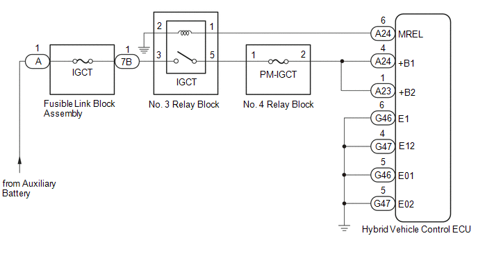
DESCRIPTION If the power
switch is on (IG), the hybrid vehicle control ECU applies current to the
MREL terminal to turn the IGCT relay on. This supplies power to the +B1
and +B2 terminals. WIRING DIAGRAM
 CAUTION / NOTICE / HINT
NOTICE: After
turning the power switch off, waiting time may be required before
disconnecting the cable from the negative (-) auxiliary battery
terminal. Therefore, make sure to read the disconnecting the cable from
the negative (-) auxiliary battery terminal notices before proceeding
with work. Click here  PROCEDURE
| 1. |
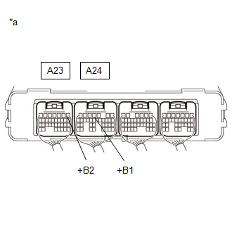
CHECK HYBRID VEHICLE CONTROL ECU (+B1, +B2 VOLTAGE) |
(a) Turn the power switch on (IG).
| (b) Measure the voltage according to the value(s) in the table below.
Standard Voltage: |
Tester Connection | Condition |
Specified Condition | |
A24-4 (+B1) - Body ground |
Power switch on (IG) |
11 to 14 V | |
A23-1 (+B2) - Body ground |
Power switch on (IG) |
11 to 14 V | |
 |
|
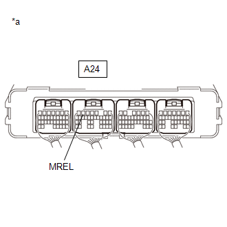
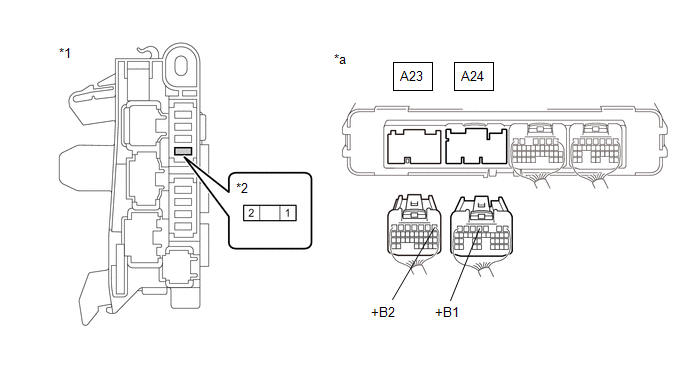
*a | Component with harness connected
(Hybrid Vehicle Control ECU) | | |
(c) Turn the power switch off.
| NG |  |
GO TO STEP 3 |
|
OK |
 | |
| 2. |
CHECK HARNESS AND CONNECTOR (HYBRID VEHICLE CONTROL ECU - BODY GROUND) |
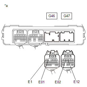
(a) Disconnect the G46 and G47 hybrid vehicle control ECU connectors.
| (b) Measure the resistance according to the value(s) in the table below.
Standard Resistance: |
Tester Connection | Condition |
Specified Condition | |
G46-6 (E1) - Body ground |
Always | Below 1 Ω | |
G46-5 (E01) - Body ground |
Always | Below 1 Ω | |
G47-5 (E02) - Body ground |
Always | Below 1 Ω | |
G47-4 (E12) - Body ground |
Always | Below 1 Ω | |
 |
|
*a | Rear view of wire harness connector
(to Hybrid Vehicle Control ECU) | | |
(c) Reconnect the G46 and G47 hybrid vehicle control ECU connectors.
| OK |
| GO TO PROBLEM SYMPTOMS TABLE |
| NG |
| REPAIR OR REPLACE HARNESS OR CONNECTOR |
| 3. |
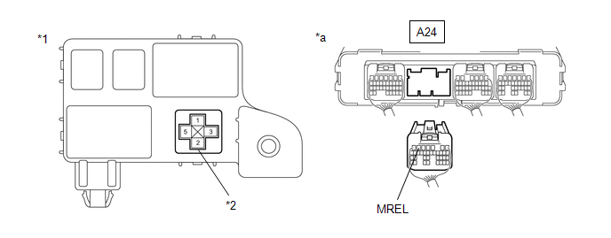
CHECK HYBRID VEHICLE CONTROL ECU (MREL VOLTAGE) |
(a) Turn the power switch on (IG).
| (b) Measure the voltage according to the value(s) in the table below.
Standard Voltage: |
Tester Connection | Condition |
Specified Condition | |
A24-6 (MREL) - Body ground |
Power switch on (IG) |
11 to 14 V | |
 |
|
*a | Component with harness connected
(Hybrid Vehicle Control ECU) | | |
(c) Turn the power switch off.
| NG | |
REPLACE HYBRID VEHICLE CONTROL ECU |
|
OK | |
| |
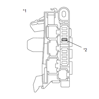
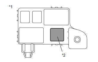
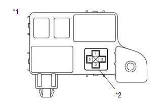
| (a) Remove the PM-IGCT fuse from the No. 4 relay block. |
 |
|
*1 | No. 4 Relay Block | |
*2 | PM-IGCT Fuse | | |
(b) Measure the resistance according to the value(s) in the table below.
Standard Resistance: |
Tester Connection | Condition |
Specified Condition | |
PM-IGCT fuse | Always |
Below 1 Ω | (c) Install the PM-IGCT fuse.
| NG |
| GO TO STEP 12 |
|
OK | |
| |
| 5. |
CHECK FUSIBLE LINK BLOCK ASSEMBLY (IGCT FUSE) |
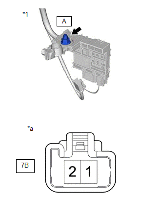
(a) Disconnect the cable from the negative (-) auxiliary battery terminal.
(b) Disconnect the cable from the positive (+) auxiliary battery terminal.
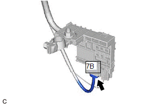
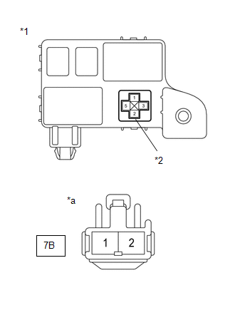
| (c) Disconnect the 7B fusible link block assembly connector. |
|
| (d) Measure the resistance according to the value(s) in the table below.
Standard Resistance: |
Tester Connection | Condition |
Specified Condition | |
7B-1 - A-1 (Positive (+) auxiliary battery terminal) |
Power switch off |
Below 1 Ω | |
 |
|
*1 | Fusible Link Block Assembly | |
*a | Component without harness connected
(Fusible Link Block Assembly) | | |
(e) Reconnect the 7B fusible link block assembly connector. (f) Reconnect the cable to the positive (+) auxiliary battery terminal.
(g) Reconnect the cable to the negative (-) auxiliary battery terminal.
| NG |
| GO TO STEP 13 |
|
OK | |
| |
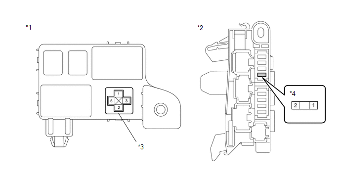
| (a) Remove the IGCT relay from the No. 3 relay block. |
 |
|
*1 | No. 3 Relay Block | |
*2 | IGCT Relay | | |
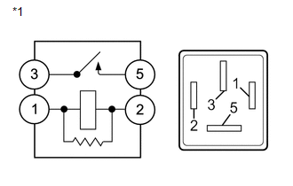
| (b) Measure the resistance according to the value(s) in the table below.
Standard Resistance: |
Tester Connection | Condition |
Specified Condition | |
3 - 5 | Auxiliary battery voltage not applied between terminals 1 and 2 |
10 kΩ or higher | |
Auxiliary battery voltage applied between terminals 1 and 2 |
Below 1 Ω | | |
(c) Install the IGCT relay.
| NG | |
REPLACE RELAY (IGCT) |
|
OK | |
| |
| 7. |
CHECK HARNESS AND CONNECTOR (NO. 4 RELAY BLOCK - HYBRID VEHICLE CONTROL ECU) |
(a) Disconnect the A23 and A24 hybrid vehicle control ECU connectors. (b) Remove the PM-IGCT fuse from the No. 4 relay block.
(c) Measure the resistance according to the value(s) in the table below.
|
*1 | No. 4 Relay Block |
*2 | PM-IGCT Fuse Holder | |
*a | Rear view of wire harness connector
(to Hybrid Vehicle Control ECU) |
- | - |
Standard Resistance: |
Tester Connection | Condition |
Specified Condition | |
A24-4 (+B1) - 2 (PM-IGCT fuse holder) |
Always | Below 1 Ω | |
A23-1 (+B2) - 2 (PM-IGCT fuse holder) |
Always | Below 1 Ω |
(d) Reconnect the A23 and A24 hybrid vehicle control ECU connectors. (e) Install the PM-IGCT fuse.
| NG |
| REPAIR OR REPLACE HARNESS OR CONNECTOR |
|
OK | |
| |
| 8. |
CHECK HARNESS AND CONNECTOR (NO. 3 RELAY BLOCK - NO. 4 RELAY BLOCK) |
(a) Remove the IGCT relay from the No. 3 relay block. (b) Remove the PM-IGCT fuse from the No. 4 relay block.
(c) Measure the resistance according to the value(s) in the table below.
|
*1 | No. 3 Relay Block |
*2 | No. 4 Relay Block | |
*3 | IGCT Relay Holder |
*4 | PM-IGCT Fuse Holder |
Standard Resistance: |
Tester Connection | Condition |
Specified Condition | |
5 (IGCT relay holder) - 1 (PM-IGCT fuse holder) |
Always | Below 1 Ω |
(d) Install the PM-IGCT fuse. (e) Install the IGCT relay.
| NG |
| REPAIR OR REPLACE HARNESS OR CONNECTOR |
|
OK | |
| |
| 9. |
CHECK HARNESS AND CONNECTOR (FUSIBLE LINK BLOCK ASSEMBLY - NO. 3 RELAY BLOCK) |
(a) Disconnect the 7B fusible link block assembly connector.
| (b) Remove the IGCT relay from the No. 3 relay block. |
 |
|
*1 | No. 3 Relay Block | |
*2 | IGCT Relay Holder | |
*a | Front view of wire harness connector
(to Fusible Link Block Assembly) | | |
(c) Measure the resistance according to the value(s) in the table below.
Standard Resistance: |
Tester Connection | Condition |
Specified Condition | |
3 (IGCT relay holder) - 7B-1 |
Always | Below 1 Ω |
(d) Install the IGCT relay. (e) Reconnect the 7B fusible link block assembly connector.
| NG |
| REPAIR OR REPLACE HARNESS OR CONNECTOR |
|
OK | |
| |
| 10. |
CHECK HARNESS AND CONNECTOR (HYBRID VEHICLE CONTROL ECU - NO. 3 RELAY BLOCK) |
(a) Disconnect the A24 hybrid vehicle control ECU connector. (b) Remove the IGCT relay from the No. 3 relay block.
(c) Measure the resistance according to the value(s) in the table below.
|
*1 | No. 3 Relay Block |
*2 | IGCT Relay Holder | |
*a | Rear view of wire harness connector
(to Hybrid Vehicle Control ECU) |
- | - |
Standard Resistance: |
Tester Connection | Condition |
Specified Condition | |
A24-6 (MREL) - 1 (IGCT relay holder) |
Always | Below 1 Ω | |
A24-6 (MREL) or 1 (IGCT relay holder) - Body ground and other terminals |
Always | 10 kΩ or higher |
(d) Install the IGCT relay. (e) Reconnect the A24 hybrid vehicle control ECU connector.
| NG |
| REPAIR OR REPLACE HARNESS OR CONNECTOR |
|
OK | |
| |
| 11. |
CHECK HARNESS AND CONNECTOR (NO. 3 RELAY BLOCK - BODY GROUND) |
(a) Remove the IGCT relay from the No. 3 relay block.
| (b) Measure the resistance according to the value(s) in the table below.
Standard Resistance: |
Tester Connection | Condition |
Specified Condition | |
2 (IGCT relay holder) - Body ground |
Always | Below 1 Ω | |
 |
|
*1 | No. 3 Relay Block | |
*2 | IGCT Relay Holder | | |
(c) Install the IGCT relay.
| OK | |
CHECK FOR INTERMITTENT PROBLEMS |
| NG |
| REPAIR OR REPLACE HARNESS OR CONNECTOR |
| 12. |
CHECK HARNESS AND CONNECTOR (NO. 4 RELAY BLOCK - HYBRID VEHICLE CONTROL ECU) |
(a) Remove the PM-IGCT fuse from the No. 4 relay block. (b) Disconnect the A23 and A24 hybrid vehicle control ECU connectors.
(c) Measure the resistance according to the value(s) in the table below.
|
*1 | No. 4 Relay Block |
*2 | PM-IGCT Fuse Holder | |
*a | Rear view of wire harness connector
(to Hybrid Vehicle Control ECU) |
- | - |
Standard Resistance: |
Tester Connection | Condition |
Specified Condition | |
A24-4 (+B1) or 2 (PM-IGCT fuse holder) - Body ground and other terminals |
Always | 10 kΩ or higher | |
A23-1 (+B2) or 2 (PM-IGCT fuse holder) - Body ground and other terminals |
Always | 10 kΩ or higher |
(d) Reconnect the A23 and A24 hybrid vehicle control ECU connectors. (e) Install the PM-IGCT fuse.
| OK |
| REPLACE FUSE (PM-IGCT) |
| NG |
| GO TO STEP 15 |
| 13. |
CHECK HARNESS AND CONNECTOR (FUSIBLE LINK BLOCK ASSEMBLY - NO. 3 RELAY BLOCK) |
(a) Disconnect the 7B fusible link block assembly connector. (b) Remove the IGCT relay from the No. 3 relay block.
| (c) Measure the resistance according to the value(s) in the table below. Standard Resistance: |
Tester Connection | Condition |
Specified Condition | |
3 (IGCT relay holder) or 7B-1 - Body ground and other terminals |
Always | 10 kΩ or higher | |
|
|
|
*1 | No. 3 Relay Block | |
*2 | IGCT Relay Holder | |
*a | Front view of wire harness connector
(to Fusible Link Block Assembly) | | |
(d) Install the IGCT relay. (e) Reconnect the 7B fusible link block assembly connector.
| NG |
| GO TO STEP 16 |
|
OK | |
| |
| 14. |
CHECK HARNESS AND CONNECTOR (NO. 3 RELAY BLOCK - NO. 4 RELAY BLOCK) |
(a) Remove the IGCT relay from the No. 3 relay block. (b) Remove the PM-IGCT fuse from the No. 4 relay block.
(c) Measure the resistance according to the value(s) in the table below.
|
*1 | No. 3 Relay Block |
*2 | No. 4 Relay Block | |
*3 | IGCT Relay Holder |
*4 | PM-IGCT Fuse Holder |
Standard Resistance: |
Tester Connection | Condition |
Specified Condition | |
5 (IGCT relay holder) or 1 (PM-IGCT fuse holder) - Body ground and other terminals |
Always | 10 kΩ or higher |
(d) Install the PM-IGCT fuse. (e) Install the IGCT relay.
| OK |
| REPLACE FUSIBLE LINK BLOCK ASSEMBLY (IGCT FUSE) |
| NG |
| GO TO STEP 17 |
| 15. |
REPAIR OR REPLACE HARNESS OR CONNECTOR |
| NEXT |
| REPLACE FUSE (PM-IGCT) |
| 16. |
REPAIR OR REPLACE HARNESS OR CONNECTOR |
| NEXT |
| REPLACE FUSIBLE LINK BLOCK ASSEMBLY (IGCT FUSE) |
| 17. |
REPAIR OR REPLACE HARNESS OR CONNECTOR |
| NEXT |
| REPLACE FUSIBLE LINK BLOCK ASSEMBLY (IGCT FUSE) | |