Toyota Avalon (XX50) 2019-2022 Service & Repair Manual: Drive Motor "A" Control Module Unexpected Operation (P0A1B94)

Toyota Avalon (XX50) 2019-2022 Service & Repair Manual / Engine / Hybrid / Battery Control / Hybrid Control System / Drive Motor "A" Control Module Unexpected Operation (P0A1B94)

DTC SUMMARY

MALFUNCTION DESCRIPTION

The hybrid vehicle control ECU monitors the motor generator control ECU (MG ECU).

The cause of this malfunction may be the following:

Motor generator control ECU internal malfunction
  • Motor generator control ECU (MG ECU) malfunction

DESCRIPTION

The hybrid vehicle control ECU monitors the motor generator control ECU (MG ECU) and stores this DTC when it detects a malfunction.

DTC No.

Detection Item

DTC Detection Condition

Trouble Area

MIL

Warning Indicate

P0A1B94

Drive Motor "A" Control Module Unexpected Operation

The motor generator control ECU (MG ECU) value received by the hybrid vehicle control ECU exceeds the threshold for a certain period of time.

(1 trip detection logic)

  • Inverter with converter assembly
  • Fusible link block assembly (IGCT fuse)
  • IGCT relay

Comes on

Master Warning Light:

Comes on

MONITOR DESCRIPTION

The hybrid vehicle control ECU monitors the motor generator control ECU (MG ECU). If the internal operation is malfunctioning, the hybrid vehicle control ECU illuminates the MIL and stores a DTC.

MONITOR STRATEGY

Related DTCs

P0A1B (INF P0A1B94): Drive motor "A" control module

Required sensors/components

Inverter with converter assembly (MG ECU)

Frequency of operation

Continuous

Duration

TMC's intellectual property

MIL operation

1 driving cycle

Sequence of operation

None

TYPICAL ENABLING CONDITIONS

The monitor will run whenever the following DTCs are not stored

TMC's intellectual property

Other conditions belong to TMC's intellectual property

-

TYPICAL MALFUNCTION THRESHOLDS

TMC's intellectual property

-

COMPONENT OPERATING RANGE

Hybrid vehicle control ECU

DTC P0A1B (INF P0A1B94) is not detected

CONFIRMATION DRIVING PATTERN

HINT:

  • After repair has been completed, clear the DTC and then check that the vehicle has returned to normal by performing the following All Readiness check procedure.

    Click here

  • When clearing the permanent DTCs, refer to the "CLEAR PERMANENT DTC" procedure.

    Click here

  1. Connect the Techstream to the DLC3.
  2. Turn the power switch on (IG) and turn the Techstream on.
  3. Clear the DTCs (even if no DTCs are stored, perform the clear DTC procedure).
  4. Turn the power switch off and wait for 2 minutes or more.
  5. Turn the power switch on (IG) and turn the Techstream on.
  6. With power switch on (IG) and wait for 2 minutes or more. [*1]

    HINT:

    • If the vehicle has returned to normal, it can be driven after turning the power switch on (READY).
    • [*1] : Normal judgment procedure.

      The normal judgment procedure is used to complete DTC judgment and also used when clearing permanent DTCs.

  7. Enter the following menus: Powertrain / Hybrid Control / Utility / All Readiness.
  8. Check the DTC judgment result.

    HINT:

    • If the judgment result shows NORMAL, the system is normal.
    • If the judgment result shows ABNORMAL, the system has a malfunction.
    • If the judgment result shows INCOMPLETE or N/A, perform the normal judgment procedure again.

WIRING DIAGRAM

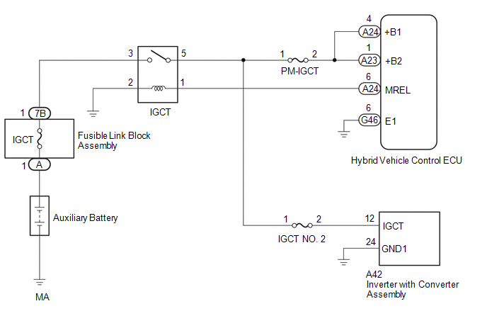
CAUTION / NOTICE / HINT

NOTICE:

After turning the power switch off, waiting time may be required before disconnecting the cable from the negative (-) auxiliary battery terminal. Therefore, make sure to read the disconnecting the cable from the negative (-) auxiliary battery terminal notices before proceeding with work.

Click here

PROCEDURE

1.

CHECK AUXILIARY BATTERY TERMINAL (CONTACT PROBLEM)

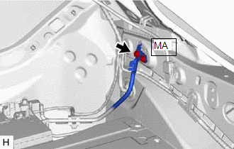
(a) Check the connection of the negative (-) and positive (+) auxiliary battery terminals.

OK:

The terminals are connected securely and there is no contact problem.

HINT:

If performing a reproduction test, turn the power switch on (IG) and shake the wire harnesses vertically and horizontally before checking for DTCs.

NG

GO TO STEP 6

OK

2.

CHECK GROUND WIRE CONNECTION CONDITION

(a) Check the installation condition of the ground wires MA.

OK:

The ground wires MA are securely installed.

HINT:

If performing a reproduction test, turn the power switch on (IG) and shake the wire harnesses vertically and horizontally before checking for DTCs.

NG

GO TO STEP 7

OK

3.

CHECK FUSIBLE LINK (IGCT)

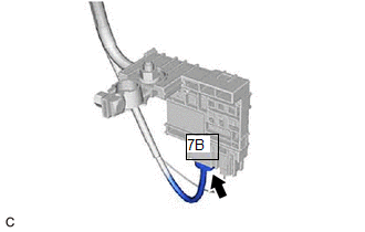
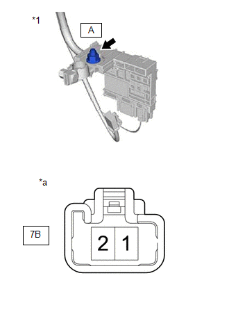
(a) Disconnect the cable from the negative (-) auxiliary battery terminal.

(b) Disconnect the cable from the positive (+) auxiliary battery terminal.

(c) Check the fusible link block assembly (IGCT) for improper installation.

OK:

The fusible link block assembly is installed securely and there is no contact problem.

(d) Disconnect the 7B fusible link block assembly connector.

(e) Measure the resistance according to the value(s) in the table below.

Standard Resistance:

Tester Connection

Condition

Specified Condition

7B-1 - A-1 (Positive (+) auxiliary battery terminal)

Power switch off

Below 1 Ω

*1

Fusible Link Block Assembly

*a

Component without harness connected

(Fusible Link Block Assembly)

(f) Reconnect the 7B fusible link block assembly connector.

(g) Reconnect the cable from the positive (+) auxiliary battery terminal.

(h) Reconnect the cable from the negative (-) auxiliary battery terminal.

NG

GO TO STEP 8

OK

4.

CHECK RELAY (IGCT)

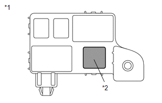
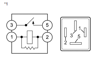
(a) Check the IGCT relay for improper installation.

OK:

The relay is installed securely.

HINT:

If performing a reproduction test, turn the power switch on (IG) and gently vibrate the IGCT relay with a finger before checking for DTCs.

(b) Remove the IGCT relay from the No. 3 relay block.

*1

No. 3 Relay Block

*2

IGCT Relay

(c) Measure the resistance according to the value(s) in the table below.

Standard Resistance:

Tester Connection

Condition

Specified Condition

3 - 5

Auxiliary battery voltage not applied between terminals 1 and 2

10 kΩ or higher

Auxiliary battery voltage applied between terminals 1 and 2

Below 1 Ω

*1

IGCT Relay

(d) Install the IGCT relay.

NG

GO TO STEP 9

OK

5.

CHECK DTC OUTPUT (HYBRID CONTROL)

(a) Connect the Techstream to the DLC3.

(b) Turn the power switch on (IG).

(c) Enter the following menus: Powertrain / Hybrid Control / Trouble Codes.

(d) Check for DTCs.

HINT:

Check the DTCs that were output when the vehicle was brought to the workshop.

Powertrain > Hybrid Control > Trouble Codes

Result

Proceed to

P0A1B94 only is output

A

DTCs except P0A1B94 are output

B

(e) Turn the power switch off.

A

REPLACE INVERTER WITH CONVERTER ASSEMBLY

B

GO TO DTC CHART (HYBRID CONTROL SYSTEM)

6.

CONNECT SECURELY

NEXT

GO TO STEP 10

7.

CONNECT SECURELY

NEXT

GO TO STEP 10

8.

REPAIR OR REPLACE MALFUNCTIONING PARTS

NEXT

GO TO STEP 10

9.

REPAIR OR REPLACE MALFUNCTIONING PARTS

NEXT

10.

CLEAR DTC

Click here

NEXT

11.

SIMULATION TEST

(a) Turn the power switch off and wait for 2 minutes or more.

(b) Turn the power switch on (IG) and wait for 2 minutes or more.

(c) Turn the power switch off.

NEXT

12.

CHECK DTC OUTPUT (HYBRID CONTROL)

(a) Connect the Techstream to the DLC3.

(b) Turn the power switch on (IG).

(c) Enter the following menus: Powertrain / Hybrid Control / Trouble Codes.

Powertrain > Hybrid Control > Trouble Codes

(d) Check for DTCs.

Result

Proceed to

No DTCs are output

A

P0A1B94 only is output

B

DTCs except P0A1B94 are output

C

(e) Turn the power switch off.

A

END

B

REPLACE INVERTER WITH CONVERTER ASSEMBLY

C

GO TO DTC CHART (HYBRID CONTROL SYSTEM)

    Drive Motor "A" Control Module Internal Electronic Failure (P0A1B49)

    Drive Motor "A" Temperature Sensor Voltage Out of Range (P0A2A1C,P0A2A1F)

    See More:

    Toyota Avalon (XX50) 2019-2022 Service & Repair Manual > Power Tilt And Power Telescopic Steering Column System(for Gasoline Model): Freeze Frame Data
    FREEZE FRAME DATA FREEZE FRAME DATA NOTICE: Freeze frame data values will vary depending on the measurement conditions, surroundings, or vehicle conditions. For this reason, there may be a problem even when the values are within specifications. Turn the engine switch on (IG) and park the vehicle on ...

    Toyota Avalon (XX50) 2019-2022 Owners Manual

    Toyota Avalon (XX50) 2019-2022 Service & Repair Manual

    © 2024 Copyright www.tavalon.net
    0.0135