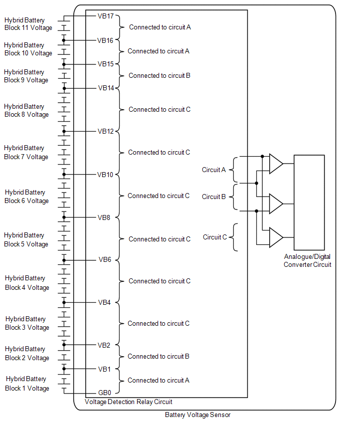
DESCRIPTION The hybrid
vehicle control ECU controls the SOC (state of charge) of the HV battery
at a constant level during driving. The HV battery is composed of 34
modules, and each module consists of six 1.2 V cells in series. The
battery voltage sensor monitors battery block voltage at 11 locations.
 |
DTC No. | Detection Item |
DTC Detection Condition | Trouble Area |
MIL | Warning Indicate | |
P1AC000 | Hybrid/EV Battery Cell Low Voltage |
Voltage difference between battery blocks is larger than the specified value due to an internal malfunction of the HV battery.
(2 trip detection logic) |
- Battery voltage sensor
- HV battery
- Hybrid battery terminal block
| Comes on |
Master Warning Light: Comes on | Related Data List |
DTC No. | Data List | |
P1AC000 |
- Hybrid Battery Block 1 to 11 Voltage*1
- Hybrid Battery SOC
|
HINT:
- *1: Under normal conditions, the values of Hybrid Battery Block 1, 2, 9,
10 and 11 Voltage will be approximately 16 V and Hybrid Battery Block
3, 4, 5, 6, 7 and 8 Voltage will be approximately 32 V.
- If there is a short or open in a battery block voltage detection line,
the value of Hybrid Battery Block Voltage for the corresponding battery
block will be lower than 8 V.
The following items can be helpful when performing repairs: Data List
- Internal Resistance 1 to 11
- Ready Signal
- Vehicle Speed
- Accelerator Position
- Shift Position
- Engine Speed
- Hybrid Battery Voltage
- Hybrid Battery Current
- BATT Voltage
- Hybrid Battery SOC just after IG-ON
- Hybrid Battery Maximum SOC
- Hybrid Battery Minimum SOC
- Total Distance Traveled
- Distance from DTC Cleared
- Engine Run Time
Vehicle Control History Data
- Hybrid Battery Voltage Low
HINT:
- This DTC can be stored after clearing DTCs and driving the vehicle for
approximately 10 minutes. (As 2 trip detection logic is used, check for
DTCs including pending DTCs.)
- DTC P1AC000 is stored when a malfunction is detected in the HV battery
or battery voltage sensor. If the HV battery is malfunctioning, the
malfunction may not be reproduced when the condition of the HV battery
changes due to a difference in driving load (amperage), battery SOC and
battery temperature. Therefore, use the freeze frame data when
performing a repair.
- When the HV battery is malfunctioning:
- - Voltage of 1 or few battery blocks has dropped. The difference of
voltage value between the hybrid battery block 1 and 2, 3 and 4, 4 and
5, 5 and 6, 6 and 7, 7 and 8, 9 and 10 or 10 and 11 is 1.2 V or more.
- - Voltage of all battery blocks is output randomly with no certain pattern.
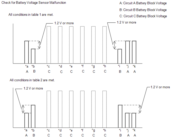
- When the battery voltage sensor is malfunctioning:
- - Differences in battery block voltages have a certain pattern.
- In order to ensure HV battery performance, appropriate cooling
performance must be maintained. Perform the following items as
necessary. If cooling performance has decreased and "Maintenance
Required for Traction Battery Cooling Parts See Owner's Manual" is
displayed on the multi-information display, make sure to perform the
following items:
- Make sure the air intake port is not blocked.
- Make sure there are no gaps between the connecting parts of the ducts.
- Clean the No. 1 HV battery intake filter.
- Clear the DTCs to reset the learning values even if no DTCs are stored.
MONITOR DESCRIPTION The
battery voltage sensor, which monitors the voltage of the battery
blocks, determines that a malfunction has occurred if a voltage
difference between the battery blocks exceeds the standard. When the
malfunction detection condition is satisfied, the hybrid vehicle control
ECU will illuminate the MIL and store a DTC. MONITOR STRATEGY |
Related DTCs | P1AC0 (INF P1AC000): Battery cell malfunction | |
Required sensors/components | Main: Battery voltage sensor
Sub: Battery current sensor, battery temperature sensor | |
Frequency of operation | Continuous | |
Duration | TMC's intellectual property | |
MIL operation | 2 driving cycles | |
Sequence of operation | None | TYPICAL ENABLING CONDITIONS |
The monitor will run whenever the following DTCs are not stored |
TMC's intellectual property | | Other conditions belong to TMC's intellectual property |
- | TYPICAL MALFUNCTION THRESHOLDS |
TMC's intellectual property | - | COMPONENT OPERATING RANGE |
Battery voltage sensor | DTC P1AC0 (INF P1AC000) is not detected | CONFIRMATION DRIVING PATTERN
HINT:
- After repair has been completed, clear the DTC and then check that the
vehicle has returned to normal by performing the following All Readiness
check procedure.
Click here 
- When clearing the permanent DTCs, refer to the "CLEAR PERMANENT DTC" procedure.
Click here
- Connect the Techstream to the DLC3.
- Turn the power switch on (IG) and turn the Techstream on.
- Clear the DTCs (even if no DTCs are stored, perform the clear DTC procedure).
- Turn the power switch off and wait for 2 minutes or more.
- Turn the power switch on (IG) and turn the Techstream on.
- Drive the vehicle on urban roads for approximately 10 minutes.[*1]
HINT:
- Enter the following menus: Powertrain / Hybrid Control / Utility / All Readiness.
- Check the DTC judgment result.
HINT:
- If the judgment result shows NORMAL, the system is normal.
- If the judgment result shows ABNORMAL, the system has a malfunction.
- If the judgment result shows INCOMPLETE or N/A, perform the normal judgment procedure again.
CAUTION / NOTICE / HINT
CAUTION:
- Before the following operations are conducted, take precautions to
prevent electric shock by turning the power switch off, wearing
insulated gloves, and removing the service plug grip from HV battery.
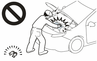
- Inspecting the high-voltage system
- Disconnecting the low voltage connector of the inverter with converter assembly
- Disconnecting the low voltage connector of the HV battery
- To prevent electric shock, make sure to remove the service plug grip to
cut off the high voltage circuit before servicing the vehicle.
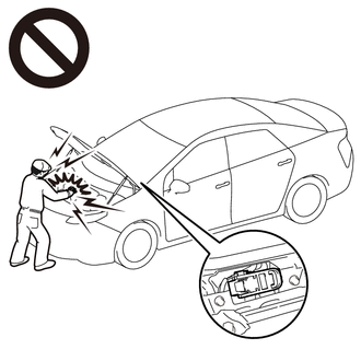
- After removing the service plug grip from the HV battery, put it in your
pocket to prevent other technicians from accidentally reconnecting it
while you are working on the high-voltage system.

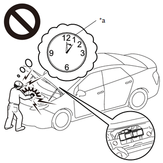
- After removing the service plug grip, wait for at least 10 minutes
before touching any of the high-voltage connectors or terminals. After
waiting for 10 minutes, check the voltage at the terminals in the
inspection point in the inverter with converter assembly. The voltage
should be 0 V before beginning work.
Click here
|
*a |
Without waiting for 10 minutes |
HINT:
Waiting for at least 10 minutes is required to discharge the high-voltage capacitor inside the inverter with converter assembly.
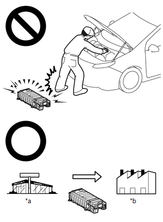
- Make sure to insulate the high-voltage connectors and terminals of the HV battery with insulating tape after removing it.
If the HV battery stored without insulating the connectors and terminals, electric shock or fire may result.
- When disposing of an HV battery, make sure to return it through an
authorized collection agent who is capable of handling it safely. If the
HV battery is returned via the manufacturer specified route, it will be
returned properly and in a safe manner by an authorized collection
agent.
|
*a |
Dealer |
|
*b |
Battery Collection Agent |
- Accidents such as electric shock may result if the HV battery is
disposed of improperly or abandoned. Therefore, make sure to return all
HV batteries through an authorized collection agent.
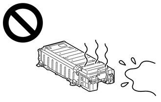
- After removing the HV battery, keep it away from water. Exposure to
water may cause the HV battery to produce heat, resulting in a fire.
NOTICE: After
turning the power switch off, waiting time may be required before
disconnecting the cable from the negative (-) auxiliary battery
terminal. Therefore, make sure to read the disconnecting the cable from
the negative (-) auxiliary battery terminal notices before proceeding
with work. Click here PROCEDURE
| 1. |
CHECK DTC OUTPUT (HYBRID CONTROL) | (a) Connect the Techstream to the DLC3.
(b) Turn the power switch on (IG). (c) Enter the following menus: Powertrain / Hybrid Control / Trouble Codes.
(d) Check for DTCs. Powertrain > Hybrid Control > Trouble Codes
|
Result | Proceed to | |
P0AFC00, P0AFC96, P308A12 or P0AFC62 is not output. |
A | | P0AFC00, P0AFC96, P308A12 or P0AFC62 is output. |
B | (e) Turn the power switch off.
| B |
 | GO TO DTC CHART (HYBRID CONTROL SYSTEM) |
|
A |
 | |
| 2. |
CHECK FREEZE FRAME DATA | (a) Connect the Techstream to the DLC3.
(b) Turn the power switch on (IG). (c) Enter the following menus: Powertrain / Hybrid Control / Trouble Codes.
(d) Read output DTCs. Powertrain > Hybrid Control > Trouble Codes
(e) Using the Techstream, make a note of the freeze frame data item "Hybrid Battery Block 3 to 8 Voltage".
(f)
Compare the freeze frame data item "Hybrid Battery Block 3 to 8
Voltage" values with those shown in the following combination tables. |
Condition | | "Hybrid Battery Block 3 Voltage" - "Hybrid Battery Block 4 Voltage" = 1.2 V or more | |
"Hybrid Battery Block 4 Voltage" - "Hybrid Battery Block 3 Voltage" = 1.2 V or more | |
"Hybrid Battery Block 4 Voltage" - "Hybrid Battery Block 5 Voltage" = 1.2 V or more | |
"Hybrid Battery Block 5 Voltage" - "Hybrid Battery Block 4 Voltage" = 1.2 V or more | |
"Hybrid Battery Block 5 Voltage" - "Hybrid Battery Block 6 Voltage" = 1.2 V or more | |
"Hybrid Battery Block 6 Voltage" - "Hybrid Battery Block 5 Voltage" = 1.2 V or more | |
"Hybrid Battery Block 6 Voltage" - "Hybrid Battery Block 7 Voltage" = 1.2 V or more | |
"Hybrid Battery Block 7 Voltage" - "Hybrid Battery Block 6 Voltage" = 1.2 V or more | |
"Hybrid Battery Block 7 Voltage" - "Hybrid Battery Block 8 Voltage" = 1.2 V or more | |
"Hybrid Battery Block 8 Voltage" - "Hybrid Battery Block 7 Voltage" = 1.2 V or more |
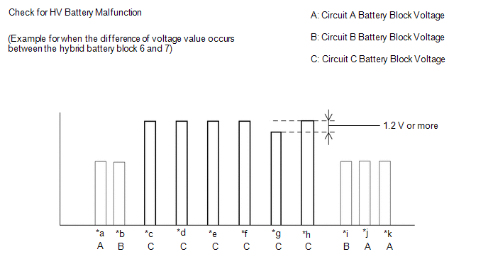
|
*a | Hybrid Battery Block 1 Voltage |
*b | Hybrid Battery Block 2 Voltage | |
*c | Hybrid Battery Block 3 Voltage |
*d | Hybrid Battery Block 4 Voltage | |
*e | Hybrid Battery Block 5 Voltage |
*f | Hybrid Battery Block 6 Voltage | |
*g | Hybrid Battery Block 7 Voltage |
*h | Hybrid Battery Block 8 Voltage | |
*i | Hybrid Battery Block 9 Voltage |
*j | Hybrid Battery Block 10 Voltage | |
*k | Hybrid Battery Block 11 Voltage |
- | - |
|
Result | Proceed to | |
On the HV battery blocks 3 to 8, one of the conditions in the table above is met. |
A | | Other than above |
B | (g) Turn the power switch off.
| B |
| GO TO STEP 5 |
|
A | |
| |
| 3. |
CHECK TOTAL DISTANCE DRIVEN | (a) Read the odometer to check the total distance the vehicle has been driven.
|
Result | Proceed to | |
Total distance driven is less than 200000 km (124280 mile) |
A | |
Total distance driven is 200000 km (124280 mile) or more |
Current
total distance driven - total distance driven when hybrid battery
terminal block replaced = less than 200000 km (124280 mile) *1 | |
Other than above | B |
HINT: *1: If the hybrid battery terminal block has been replaced, use the total distance driven since it was replaced.
| A |
| REPLACE HV BATTERY |
|
B | |
| |
Click here
| NEXT | |
REPLACE HYBRID BATTERY TERMINAL BLOCK |
| 5. |
CHECK FREEZE FRAME DATA | (a) Connect the Techstream to the DLC3.
(b) Turn the power switch on (IG). (c) Enter the following menus: Powertrain / Hybrid Control / Trouble Codes.
(d) Read output DTCs. Powertrain > Hybrid Control > Trouble Codes
(e) Using the Techstream, make a note of the freeze frame data item "Hybrid Battery Block 1, 2, 9, 10 and 11 Voltage".
(f)
Compare the freeze frame data item "Hybrid Battery Block 1, 2, 9, 10
and 11 Voltage" values with those shown in the following combination
tables. Table 1 |
Circuit A Battery Block | Circuit B Battery Block |
Condition | | Hybrid Battery Block 1 Voltage |
Hybrid Battery Block 2 Voltage |
"Hybrid Battery Block 1 Voltage" - "Hybrid Battery Block 2 Voltage" = 1.2 V or more | |
Hybrid Battery Block 10 Voltage |
Hybrid Battery Block 9 Voltage |
"Hybrid Battery Block 10 Voltage" - "Hybrid Battery Block 9 Voltage" = 1.2 V or more | |
Hybrid Battery Block 11 Voltage |
Hybrid Battery Block 9 Voltage |
"Hybrid Battery Block 11 Voltage" - "Hybrid Battery Block 9 Voltage" = 1.2 V or more | Table 2 |
Circuit A Battery Block | Circuit B Battery Block |
Condition | | Hybrid Battery Block 1 Voltage |
Hybrid Battery Block 2 Voltage |
"Hybrid Battery Block 2 Voltage" - "Hybrid Battery Block 1 Voltage" = 1.2 V or more | |
Hybrid Battery Block 10 Voltage |
Hybrid Battery Block 9 Voltage |
"Hybrid Battery Block 9 Voltage" - "Hybrid Battery Block 10 Voltage" = 1.2 V or more | |
Hybrid Battery Block 11 Voltage |
Hybrid Battery Block 9 Voltage |
"Hybrid Battery Block 9 Voltage" - "Hybrid Battery Block 11 Voltage" = 1.2 V or more |
|
*a | Hybrid Battery Block 1 Voltage |
*b | Hybrid Battery Block 2 Voltage | |
*c | Hybrid Battery Block 3 Voltage |
*d | Hybrid Battery Block 4 Voltage | |
*e | Hybrid Battery Block 5 Voltage |
*f | Hybrid Battery Block 6 Voltage | |
*g | Hybrid Battery Block 7 Voltage |
*h | Hybrid Battery Block 8 Voltage | |
*i | Hybrid Battery Block 9 Voltage |
*j | Hybrid Battery Block 10 Voltage | |
*k | Hybrid Battery Block 11 Voltage |
- | - |
HINT: If
an internal malfunction occurs in the battery voltage sensor, this
symptom (difference in voltage of 1.2 V or more for certain pairs of
blocks as shown in the illustration) will occur.
|
Result | Proceed to | |
Either of the following conditions is met: 1. All conditions in table 1 are met.
2. All conditions in table 2 are met. |
A | | Other than above |
B | (g) Turn the power switch off.
| A |
| REPLACE BATTERY VOLTAGE SENSOR |
|
B | |
| |
| 6. |
CHECK TOTAL DISTANCE DRIVEN | (a) Read the odometer to check the total distance the vehicle has been driven.
|
Result | Proceed to | |
Total distance driven is less than 200000 km (124280 mile) |
A | |
Total distance driven is 200000 km (124280 mile) or more |
Current
total distance driven - total distance driven when hybrid battery
terminal block replaced = less than 200000 km (124280 mile) *1 | |
Other than above | B |
HINT: *1: If the hybrid battery terminal block has been replaced, use the total distance driven since it was replaced.
| A |
| REPLACE HV BATTERY |
|
B | |
| |
Click here
| NEXT | |
REPLACE HYBRID BATTERY TERMINAL BLOCK | |


