REMOVAL CAUTION / NOTICE / HINT
The
necessary procedures (adjustment, calibration, initialization or
registration) that must be performed after parts are removed and
installed, or replaced during inverter with converter assembly
removal/installation are shown below. Necessary Procedures After Parts Removed/Installed/Replaced |
Replaced Part or Performed Procedure |
Necessary Procedure | Effect/Inoperative Function when Necessary Procedure not Performed |
Link | |
*: When performing learning using the Techstream.
| | Auxiliary battery terminal is disconnected/reconnected |
Perform steering sensor zero point calibration |
Lane departure alert system (w/ Steering Control) |
 | |
Pre-collision system | | Intelligent clearance sonar system* | |
Lighting System (for HV Model with Cornering Light) | |
Memorize steering angle neutral point |
Parking assist monitor system |
| |
Panoramic view monitor system |
| |
Replacement of inverter with converter assembly |
Resolver learning |
- DTCs are stored
- Slight vibration at a vehicle speed of 5 km/h (3 mph) or less
- Shock or vibration during acceleration
|
| |
Replacement of ECM | Perform Vehicle Identification Number (VIN) registration |
MIL illuminates |
|
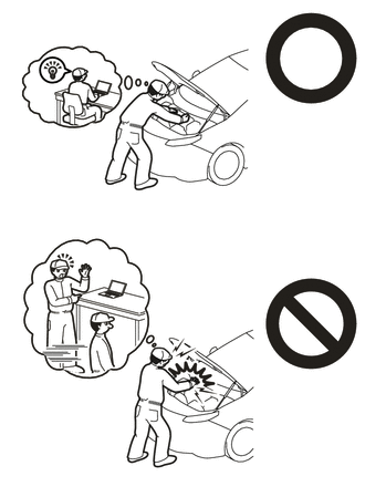
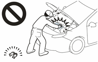
CAUTION:
NOTICE: After
turning the power switch off, waiting time may be required before
disconnecting the cable from the negative (-) auxiliary battery
terminal. Therefore, make sure to read the disconnecting the cable from
the negative (-) auxiliary battery terminal notices before proceeding
with work. Click here PROCEDURE
1. REMOVE SERVICE PLUG GRIP Click here
2. DRAIN COOLANT (for Inverter) Click here
3. REMOVE NO. 1 ENGINE COVER SUB-ASSEMBLY
Click here 4. REMOVE COOL AIR INTAKE DUCT SEAL
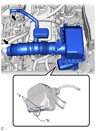
Click here 5. REMOVE INLET AIR CLEANER ASSEMBLY
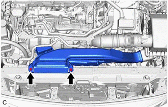
| (a) Remove the 2 bolts and inlet air cleaner assembly. |
|
6. REMOVE AIR CLEANER ASSEMBLY WITH AIR CLEANER HOSE
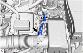
| (a) Disconnect the mass air flow meter sub-assembly connector. |
|
(b) Disengage the wire harness clamp.
| (c) Slide the clip and disconnect the No. 2 ventilation hose from the cylinder head cover sub-assembly. |
|
(d) Loosen the hose clamp and disconnect the air cleaner hose from the throttle body with motor assembly.
(e) Disengage the 2 grommets and pin to remove the air cleaner assembly with air cleaner hose.
7. REMOVE ECM Click here 8. DISCONNECT ENGINE ROOM MAIN WIRE
CAUTION: Be sure to wear insulated gloves. NOTICE: Do not allow any foreign matter or water to enter the inverter with converter assembly.
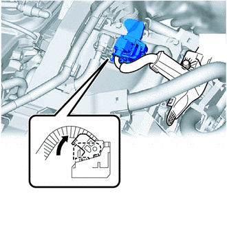
| (a) Move the lock lever while pushing the lock on the connector, and disconnect the inverter with converter assembly connector.
NOTICE:
- Do not damage the terminals, connector housing or inverter with converter assembly during disconnection.
- Cover the hole where the cable was connected with tape (non-residue type) or equivalent to prevent entry of foreign matter.
- Insulate the disconnected terminals with insulating tape.
- Do not touch the waterproof seal or terminals of the connector.
| |
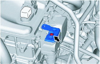
(c) Disengage the clamp and disconnect the engine room main wire. 9. REMOVE CONNECTOR COVER ASSEMBLY
CAUTION: Be sure to wear insulated gloves.
(b)
Using a T25 "TORX" socket wrench, remove the bolt (A) and connector
cover assembly from the inverter with converter assembly.
NOTICE:
- Do not touch the connector cover assembly waterproof seal.
- Do not allow any foreign matter or water to enter the inverter with converter assembly.
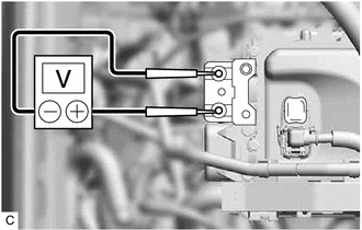
10. CHECK TERMINAL VOLTAGE CAUTION: Be sure to wear insulated gloves.
| (a) Using a voltmeter, measure the voltage between the terminals of the 2 phase connectors.
Standard Voltage: 0 V NOTICE: Do not allow any foreign matter or water to enter the inverter with converter assembly.
HINT: Use a measuring range of DC 750 V or more on the voltmeter. |
|
11. TEMPORARILY INSTALL CONNECTOR COVER ASSEMBLY CAUTION: Be sure to wear insulated gloves.
| (a) Temporarily install the connector cover assembly to the inverter with converter assembly. |
|
(b) Using a T25 "TORX" socket wrench, install the bolt. Torque:
4.5 N·m {46 kgf·cm, 40 in·lbf}
NOTICE:
- Do not touch the connector cover assembly waterproof seal.
- Do not allow any foreign matter or water to enter the inverter with converter assembly.
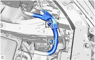
12. DISCONNECT HV FLOOR UNDER WIRE CAUTION: Be sure to wear insulated gloves.
(b) Disengage the 2 clamps and disconnect the HV floor under wire from the inverter with converter assembly
NOTICE:
- Do not touch the waterproof seal or terminals of the connector.
- Do not damage the terminals, connector housing or inverter with converter assembly during disconnection.
- Cover the hole where the cable was connected with tape (non-residue type) or equivalent to prevent entry of foreign matter.
- Do not allow any foreign matter or water to enter the inverter with converter assembly.
- Insulate the disconnected terminals with insulating tape.
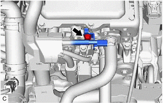
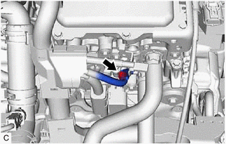
13. DISCONNECT HV AIR CONDITIONING WIRE CAUTION: Be sure to wear insulated gloves.
(b) Disengage the clamp and disconnect the HV air conditioning wire from the inverter with converter assembly.
NOTICE:
- Do not allow any foreign matter or water to enter the inverter with converter assembly.
- Do not touch the waterproof seal or terminals of the connector.
- Do not damage the terminals, connector housing or inverter with converter assembly during disconnection.
- Insulate the disconnected terminals with insulating tape.
- Cover the hole where the cable was connected with tape (non-residue type) or equivalent to prevent entry of foreign matter.
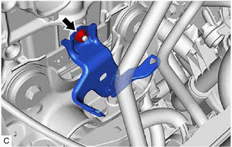
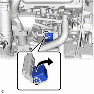
14. REMOVE WIRE HARNESS CLAMP BRACKET
| (a) Remove the nut and wire harness clamp bracket. | |
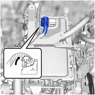
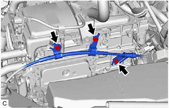
15. DISCONNECT ENGINE WIRE CAUTION: Be sure to wear insulated gloves.
NOTICE: Do not allow any foreign matter or water to enter the inverter with converter assembly.
| (a) Move the lock lever while pushing the lock on the connector, and disconnect the inverter with converter assembly connector.
NOTICE:
- Do not damage the terminals, connector housing or inverter with converter assembly during disconnection.
- Cover the hole where the cable was connected with tape (non-residue type) or equivalent to prevent entry of foreign matter.
- Insulate the disconnected terminals with insulating tape.
- Do not touch the waterproof seal or terminals of the connector.
| |
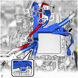
| (b) Disengage the 3 clamps (A) and disconnect the No. 1 fuel vapor feed hose. |
|
(c) Remove the bolt. (d) Disengage the 2 clamps (B).
| (e) Disengage the 2 clamps (A) and disconnect the No. 1 fuel vapor feed hose and No. 2 fuel vapor feed hose. |
|
(f) Remove the bolt. (g) Disengage the clamp (B).
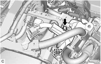
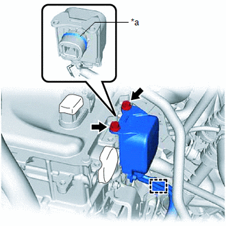
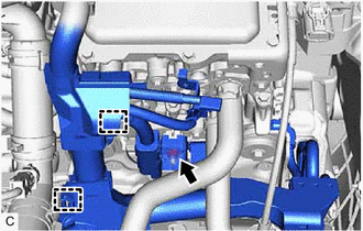
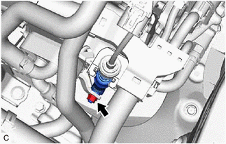
| (h) Disconnect the generator temperature sensor connector. |
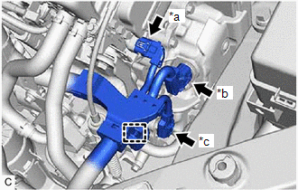 |
|
*a | Generator Temperature Sensor Connector | |
*b | Resolver (Transmission Fluid Temperature Sensor) Connector | |
*c | Shift Lever Position Sensor Connector | | |
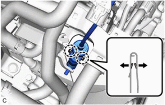
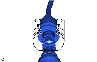
(i) Disconnect the resolver (transmission fluid temperature sensor) connector.
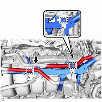
(j) Disconnect the shift lever position sensor connector. (k) Disengage the clamp.
| (l) Disengage the 2 clamps. | |
| (o) Disengage the 2 claws and open the engine wire terminal cover. |
|
(q) Disengage the 2 clamps and disconnect the engine wire from the inverter with converter assembly.
16. DISCONNECT TRANSMISSION CONTROL CABLE ASSEMBLY
| (a) Remove the nut and disconnect the transmission control cable assembly from the control shaft lever. |
|
| (b)
Using a screwdriver, disengage the 4 claws and disconnect the
transmission control cable assembly with the clip from the No. 1
transmission control cable bracket. | |
| (c) Using a screwdriver, disengage the 2 claws and remove the clip from the transmission control cable assembly. |
|
| (d) Remove the 3 bolts and disconnect the transmission control cable assembly from the inverter with converter assembly. |
|
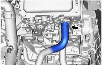
17. DISCONNECT NO. 1 INVERTER COOLING HOSE
| (a) Slide the clip and disconnect the No. 1 inverter cooling hose from the inverter with converter assembly.
NOTICE: Put
pieces of cloth into the pipe and disconnected hose or cover the pipe
and hose with plastic bags to prevent entry of foreign matter. | |
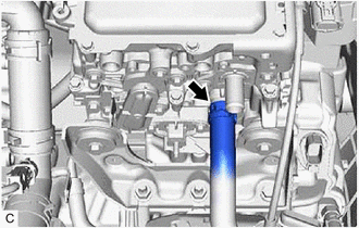
18. DISCONNECT NO. 4 INVERTER COOLING HOSE
| (a) Slide the clip and disconnect the No. 4 inverter cooling hose from the inverter with converter assembly.
NOTICE: Put
pieces of cloth into the pipe and disconnected hose or cover the pipe
and hose with plastic bags to prevent entry of foreign matter. | |
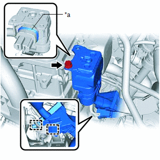
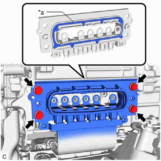
19. REMOVE INVERTER COVER CAUTION: Be sure to wear insulated gloves.
(a) Remove the 2 bolts and inverter cover from the inverter with converter assembly.
NOTICE:
- Make sure to pull the inverter cover straight out, as a connector is connected to the inside of the inverter cover.
- Do not touch the waterproof seal of the inverter cover.
- Do not allow any foreign matter or water to enter the inverter with converter assembly.
- When removing the inverter cover, do not pull the areas (A) as they may deform.
- Make sure that the interlock is installed to the inverter cover.
- Do not remove or excessively tighten the screw of the inverter cover.
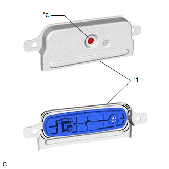
|
*1 |
Inverter Cover |
|
*a |
Screw |
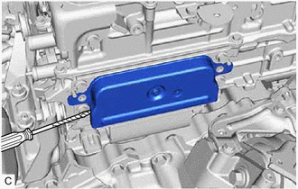
- Although the inverter cover may feel loose, this is not due to a malfunction.
HINT: If
necessary, use a screwdriver with its tip wrapped with protective tape
as shown in the illustration to remove the inverter cover.
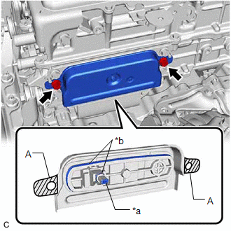
|
*a | Interlock | |
*b | Waterproof Seal |
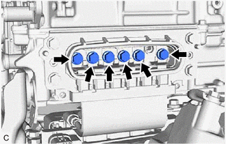
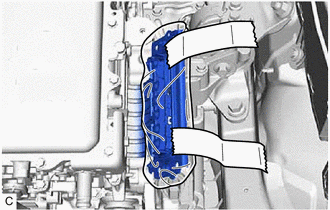
20. DISCONNECT MOTOR CABLE CAUTION: Be sure to wear insulated gloves.
| (a) Using an insulated tool, remove the 6 bolts.
NOTICE:
- Do not allow any foreign matter or water to enter the inverter with converter assembly.
- Do not touch the waterproof seal or terminals of the motor cable.
| |
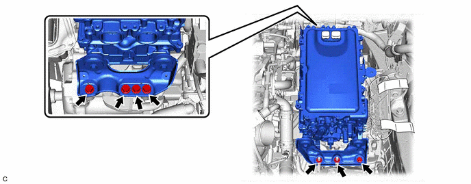
(b) Remove the 4 bolts and disconnect the motor cable from the inverter with converter assembly.
NOTICE:
- Do not allow any foreign matter or water to enter the inverter with converter assembly.
- Do not touch the waterproof seal or terminals of the motor cable.
- Do not damage the terminals, connector housing or inverter with converter assembly during disconnection.
- Insulate the disconnected terminals with insulating tape.
- After disconnecting the motor cable, wrap it with a plastic bag or equivalent to protect it.
- Cover the hole where the cable was connected with tape (non-residue type) or equivalent to prevent entry of foreign matter.
- To prevent the wire harness from being caught, make sure to bundle the wire harness using insulating tape or equivalent.
21. REMOVE INVERTER WITH CONVERTER ASSEMBLY CAUTION: Be sure to wear insulated gloves.
(a) Remove the 5 bolts, 2 nuts and inverter with converter assembly.
NOTICE:
- When removing the inverter with converter assembly, be careful not to damage the parts around it.
- To prevent damage, do not hold the inverter with converter assembly by the connectors, brackets or cooling pipes.
- To prevent damage due to static electricity, do not touch the terminals of the disconnected connectors.
HINT: Even
after the coolant is drained, coolant remains in the inverter due to its
internal structure. Therefore, seal or cover the pipes when removing
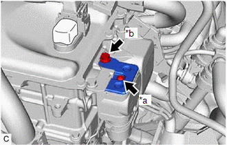
the inverter with converter assembly so that coolant does not spill out. 22. REMOVE NO. 1 INVERTER BRACKET
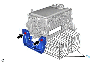
NOTICE: Make
sure to support the inverter with converter assembly at the positions
shown in the illustration, otherwise it may be damaged.
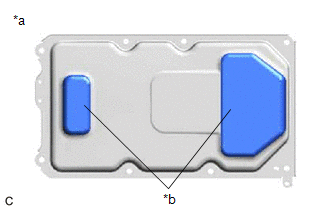
|
*a | Bottom of Inverter with Converter Assembly | |
*b | Support |
| (a) Set the inverter with converter assembly on wooden blocks. |
|
(b) Remove the 2 bolts and No. 1 inverter bracket from the inverter with converter assembly.
23. REMOVE NO. 2 INVERTER BRACKET
| (a) Remove the 2 bolts and No. 2 inverter bracket from the inverter with converter assembly. |
|
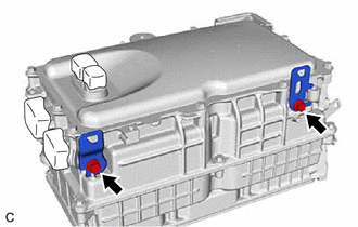
24. REMOVE WIRE HARNESS CLAMP BRACKET
| (a) Remove the 2 bolts and 2 wire harness clamp brackets from the inverter with converter assembly. |
|
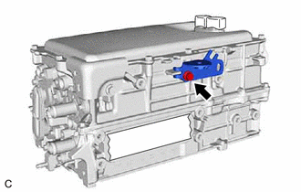
| (b) Remove the bolt and wire harness clamp bracket from the inverter with converter assembly. |
|
| (c) Remove the bolt and wire harness clamp bracket from the inverter with converter assembly. |
|
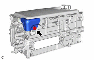
25. REMOVE INVERTER PROTECTOR
| (a) Remove the bolt and inverter protector from the inverter with converter assembly. |
| |