DTC SUMMARY MALFUNCTION DESCRIPTION If
there is a large difference between the reactor current sensor value
and the HV battery current sensor value, a malfunction will be detected. Internal inverter malfunction
- Current sensor malfunction
- Inverter with converter assembly internal circuit malfunction
DESCRIPTION |
DTC No. | Detection Item |
DTC Detection Condition | Trouble Area |
MIL | Warning Indicate | |
P1CFF62 | Hybrid/EV Battery Current/DC/DC Converter Current Signal Compare Failure |
The difference between the reactor current sensor value and the HV battery current sensor value is large.
(1 trip detection logic) |
- Inverter with converter assembly
- Wire harness or connector
| Comes on |
Master Warning Light: Comes on | Related Data List |
DTC No. | Data List | |
P1CFF62 |
- Inverter Input Current
- Hybrid/EV Battery System Current
- WIN Control Limit Power
| MONITOR DESCRIPTION
If
the motor generator control ECU detects a large difference between the
reactor current sensor value and battery current sensor value, it will
illuminate the MIL and store a DTC. MONITOR STRATEGY |
Related DTCs | P1CFF (INF P1CFF62): Hybrid/EV Battery Current/DC/DC Converter Current Correlation | |
Required sensors/components | DC/DC Converter Current Sensor Circuit | |
Frequency of operation | Continuous | |
Duration | TMC's intellectual property | |
MIL operation | 1 driving cycle | |
Sequence of operation | None | TYPICAL ENABLING CONDITIONS |
The monitor will run whenever the following DTCs are not stored |
TMC's intellectual property | | Other conditions belong to TMC's intellectual property |
- | TYPICAL MALFUNCTION THRESHOLDS |
TMC's intellectual property | - | COMPONENT OPERATING RANGE |
Motor generator control ECU | DTC P1CFF (INF P1CFF62) is not detected | CONFIRMATION DRIVING PATTERN
HINT:
- After repair has been completed, clear the DTC and then check that the
vehicle has returned to normal by performing the following All Readiness
check procedure.
Click here 
- When clearing the permanent DTCs, refer to the "CLEAR PERMANENT DTC" procedure.
Click here
- Connect the Techstream to the DLC3.
- Turn the power switch on (IG) and turn the Techstream on.
- Clear the DTCs (even if no DTCs are stored, perform the clear DTC procedure).
- Turn the power switch off and wait for 2 minutes or more.
- Turn the power switch on (IG) and turn the Techstream on.
- Turn the power switch on (IG) and wait for 5 seconds or more. [*1]
- Turn the power switch on (READY) and wait for 5 seconds or more. [*2]
- With the brake pedal depressed, depress the accelerator pedal to start the engine. [*3]
- Wait for approximately 10 seconds while depressing the brake pedal and accelerator pedal. [*4]
HINT:
[*1] to [*4]: Normal judgment procedure.
The normal judgment procedure is used to complete DTC judgment and also used when clearing permanent DTCs.
- Enter the following menus: Powertrain / Motor Generator / Utility / All Readiness.
- Check the DTC judgment result.
HINT:
- If the judgment result shows NORMAL, the system is normal.
- If the judgment result shows ABNORMAL, the system has a malfunction.
- If the judgment result shows INCOMPLETE or N/A, perform the normal judgment procedure again.
CAUTION / NOTICE / HINT
CAUTION: 
NOTICE: After
turning the power switch off, waiting time may be required before
disconnecting the cable from the negative (-) auxiliary battery
terminal. Therefore, make sure to read the disconnecting the cable from
the negative (-) auxiliary battery terminal notices before proceeding
with work. Click here PROCEDURE
(a) Connect the Techstream to the DLC3.
(b) Turn the power switch on (IG). (c) Enter the following menus: Powertrain / Hybrid Control and Motor Generator / Trouble Codes.
(d) Check for DTCs. Powertrain > Hybrid Control > Trouble Codes Powertrain > Motor Generator > Trouble Codes
|
Result | Proceed to | |
P1CFF62 only is output, or DTCs except the ones in the table below are also output. |
A | | DTCs of hybrid control system in the tables below are output. |
B | | DTCs of motor generator control system in the tables below are output. |
C | Table 1 |
Malfunction Content | System |
Relevant DTC | |
Insulation Malfunction | Hybrid control system |
P1C7C49 | Hybrid/EV Battery Voltage System Isolation (A/C Area) Internal Electronic Failure | |
P1C7D49 | Hybrid/EV Battery Voltage System Isolation (Hybrid/EV Battery Area) Internal Electronic Failure | |
P1C7E49 | Hybrid/EV Battery Voltage System Isolation (Transaxle Area) Internal Electronic Failure | |
P1C7F49 | Hybrid/EV Battery Voltage System Isolation (Direct Current Area) Internal Electronic Failure | |
HV Battery Malfunction |
Hybrid control system | P0ABF00 |
Hybrid/EV Battery Current Sensor "A" Circuit Range/Performance | |
P0ABF11 | Hybrid/EV Battery Current Sensor "A" Circuit Short to Ground | |
P0ABF15 | Hybrid/EV Battery Current Sensor "A" Circuit Short to Auxiliary Battery or Open | |
P0ABF28 | Hybrid/EV Battery Current Sensor "A" Signal Bias Level Out of Range / Zero Adjustment Failure | |
P0ABF2A | Hybrid/EV Battery Current Sensor "A" Signal Stuck In Range | |
P1C9F11 | Hybrid/EV Battery Current Sensor for Driving Control Circuit Short to Ground | |
P1C9F15 | Hybrid/EV Battery Current Sensor for Driving Control Circuit Short to Auxiliary Battery or Open | |
P1C9F1C | Hybrid/EV Battery Current Sensor for Driving Control Voltage Out of Range | |
P1CBB12 | Hybrid/EV Battery Current Sensor Power Supply Circuit Short to Auxiliary Battery | |
P1CBB14 | Hybrid/EV Battery Current Sensor Power Supply Circuit Short to Ground or Open | Table 2 |
Malfunction Content | System |
Relevant DTC | |
Microcomputer malfunction |
Motor generator control system |
P0A1A47 | Generator Control Module Watchdog / Safety μC Failure | |
P0A1A49 | Generator Control Module Internal Electronic Failure | |
P0A1B1F | Generator Control Module Circuit Intermittent | |
P1C2A1C | Generator A/D Converter Circuit Circuit Voltage Out of Range | |
P1C2A49 | Generator A/D Converter Circuit Internal Electronic Failure | |
P1C2B1C | Drive Motor "A" Control Module A/D Converter Circuit Voltage Out of Range | |
P1C2B49 | Drive Motor "A" Control Module A/D Converter Circuit Internal Electronic Failure | |
P313383 | Communication Error from Generator to Drive Motor "A" Value of Signal Protection Calculation Incorrect | |
P313386 | Communication Error from Generator to Drive Motor "A" Signal Invalid | |
P313387 | Communication Error from Generator to Drive Motor "A" Missing Message | |
P313483 | Communication Error from Drive Motor "A" to Generator Value of Signal Protection Calculation Incorrect | |
P313486 | Communication Error from Drive Motor "A" to Generator Signal Invalid | |
P313487 | Communication Error from Drive Motor "A" to Generator Missing Message | |
Hybrid control system | P0A1B49 |
Drive Motor "A" Control Module Internal Electronic Failure | |
Power source circuit malfunction |
Motor generator control system |
P06B01C | Generator Control Module Position Sensor REF Power Source Circuit Voltage Out of Range | |
P06D61C | Generator Control Module Offset Power Circuit Voltage Out of Range | |
Communication malfunction |
Motor generator control system |
P312487 | Lost Communication between Drive Motor "A" and HV ECU Missing Message | |
Hybrid control system | P312387 |
Lost Communication with Drive Motor Control Module "A" from Hybrid/EV Control Module Missing Message | |
Sensor and actuator circuit malfunction |
Motor generator control system |
P0E5111 | DC/DC Converter Current Sensor Circuit Short to Ground | |
P0E5115 | DC/DC Converter Current Sensor Circuit Short to Battery or Open | |
P0E5128 | DC/DC Converter Current Sensor Signal Bias Level Out of Range / Zero Adjustment Failure |
HINT:
- P1CFF62 may be output as a result of the malfunction indicated by the DTCs above.
- The chart above is listed in inspection order of priority.
- Check DTCs that are output at the same time by following the listed
order. (The main cause of the malfunction can be determined without
performing unnecessary inspections.)
(e) Turn the power switch off.
| B |
 | GO TO DTC CHART (HYBRID CONTROL SYSTEM) |
| C |
| GO TO DTC CHART (MOTOR GENERATOR CONTROL SYSTEM) |
|
A |
 | |
(a) Ensure the safety of the areas in front and at the back of the vehicle.
(b) Apply the parking brake and secure the wheels using chocks. (c) Connect the Techstream to the DLC3.
(d) Turn the power switch on (READY). (e) Depress the brake pedal firmly with your left foot.
(f) Move the shift lever to D. (g)
Enter the following menus: Powertrain / Motor Generator / Data List /
Hybrid/EV Battery System Current, Inverter Input Current, WIN Control
Limit Power. HINT: Perform
this procedure while making sure that the absolute value of the Data
List item WIN Control Limit Power remains higher than 20 kW. (h)
Depress the brake pedal firmly with your left foot and fully depress
the accelerator pedal for 5 seconds, and then release it. CAUTION:
Make sure to fully apply the parking brake and firmly depress the brake pedal to prevent the vehicle from moving.
(i)
According to the display on the Techstream, read the Data List and
monitor the values of "Hybrid/EV Battery System Current" and "Inverter
Input Current". 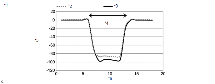
|
*1 | Change in Hybrid/EV Battery System Current and Inverter Input Current When Normal |
*2 | Hybrid/EV Battery System Current | |
*3 | Inverter Input Current |
*4 | Accelerator pedal depressed | |
*5 | Current [A] |
*6 | Time [Seconds] |
|
Result | Proceed to | |
OK | A | |
NG (Inverter Input Current Did Not Change) |
B | | NG (Hybrid/EV Battery System Current Did Not Change) |
C | (j) Turn the power switch off.
| B |
| REPLACE INVERTER WITH CONVERTER ASSEMBLY |
| C |
| GO TO DTC CHART (P0ABF00) |
|
A | |
| |
| 3. |
CHECK CONNECTOR CONNECTION CONDITION (INVERTER WITH CONVERTER ASSEMBLY CONNECTOR) |
Click here
|
Result | Proceed to | |
OK | A | |
NG (The connector is not connected securely.) |
B | | NG (The terminals are not making secure contact or are deformed, or water or foreign matter exists in the connector.) |
C |
| A |
| REPLACE INVERTER WITH CONVERTER ASSEMBLY |
| B |
| CONNECT SECURELY |
| C |
| REPAIR OR REPLACE HARNESS OR CONNECTOR | |