Toyota Avalon (XX50) 2019-2022 Service & Repair Manual: Terminals Of Ecu

TERMINALS OF ECU

*1

Inverter with Converter Assembly

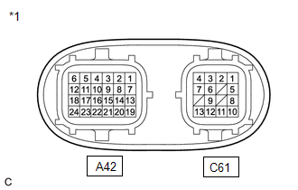
HINT:

Since the inverter with converter assembly uses waterproof connectors, the voltage and waveforms cannot be inspected directly. Standard voltage readings and waveforms are indicated for reference only.

Inverter with Converter Assembly

Terminal No.

(Symbol)

Wiring Color

Input/Output

Terminal Description

Condition

Standard Condition

A42-1 (CANH) - A42-24 (GND1)

V - W-B

Input/Output

CAN communication signal

Power switch on (IG)

Pulse generation

(Waveform 1)

A42-5 (+B2) - A42-24 (GND1)

GR - W-B

Input

Motor generator control ECU (MG ECU) power source

Power switch on (IG)

11 to 14 V

A42-6 (+B) - A42-24 (GND1)

W - W-B

Input

Motor generator control ECU (MG ECU) power source

Power switch on (IG)

11 to 14 V

A42-7 (CANL) - A42-24 (GND1)

W - W-B

Input/Output

CAN communication signal

Power switch on (IG)

Pulse generation

(Waveform 1)

A42-10 (GI) - A42-24 (GND1)

W - W-B

Input

Camshaft position sensor signal

Power switch on (READY), engine running

Pulse generation

(Waveform 2)

A42-12 (IGCT) - A42-24 (GND1)

BE - W-B

Input

Motor generator control ECU (MG ECU) power source

Power switch on (IG)

11 to 14 V

A42-17 (NE) - A42-24 (GND1)

B - W-B

Input

Crankshaft position sensor signal

Power switch on (READY), engine running

Pulse generation

(Waveform 3)

A42-19 (HMCL) - A42-24 (GND1)

W - W-B

Input/Output

Communication signal

Power switch on (IG)

Pulse generation

(Waveform 4)

A42-20 (HMCH) - A42-24 (GND1)

B - W-B

Input/Output

Communication signal

Power switch on (IG)

Pulse generation

(Waveform 4)

A42-22 (HSDN) - A42-24 (GND1)

W - W-B

Input

MG shutdown signal

Power switch on (READY)

0 to 1 V

C61-1 (MSN) - C61-2 (MSNG)

G - Y

Input

Motor resolver signal

Motor resolver running

Pulse generation

(Waveform 5)

C61-3 (MCSG) - C61-4 (MCS)

B - L

Input

Motor resolver signal

Motor resolver running

Pulse generation

(Waveform 5)

C61-5 (MRF) - C61-6 (MRFG)

W - R

Output

Motor resolver reference signal

Motor resolver running

Pulse generation

(Waveform 5)

C61-8 (GRF) - C61-9 (GRFG)

SB - V

Output

Generator resolver reference signal

Generator resolver running

Pulse generation

(Waveform 6)

C61-10 (GSN) - C61-11 (GSNG)

GR - P

Input

Generator resolver signal

Generator resolver running

Pulse generation

(Waveform 6)

C61-12 (GCSG) - C61-13 (GCS)

BR - LG

Input

Generator resolver signal

Generator resolver running

Pulse generation

(Waveform 6)

NOTICE:

Do not measure the voltage or waveform on the sealed side of the inverter with converter assembly connector. Doing so may damage the connector because the connector is waterproof.

Oscilloscope waveforms

HINT:

Oscilloscope waveforms shown in the illustrations are examples for reference only. Noise, chattering, etc. are not shown.

(a) Waveform 1 (CAN communication signal)

Item

Content

Terminal

CH1: A42-1 (CANH) - A42-24 (GND1)

CH2: A42-7 (CANL) - A42-24 (GND1)

Equipment Setting

1 V/DIV., 50 μs./DIV.

Condition

Power switch on (IG)

(b) Waveform 2 (camshaft position sensor signal)

Item

Content

Terminal

A42-10 (GI) - A42-24 (GND1)

Equipment Setting

5 V/DIV., 20 ms./DIV.

Condition

Power switch on (READY), engine running

HINT:

The wavelength becomes shorter as the engine speed increases.

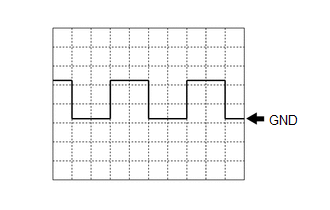
(c) Waveform 3 (crankshaft position sensor signal)

Item

Content

Terminal

A42-17 (NE) - A42-24 (GND1)

Equipment Setting

5 V/DIV., 20 ms./DIV.

Condition

Power switch on (READY), engine running

HINT:

The wavelength becomes shorter as the engine speed increases.

(d) Waveform 4 (communication signal)

Item

Content

Terminal

CH1: A42-19 (HMCL) - A42-24 (GND1)

CH2: A42-20 (HMCH) - A42-24 (GND1)

Equipment Setting

1 V/DIV., 50 μs./DIV.

Condition

Power switch on (IG)

HINT:

The waveform will vary depending on the content of the digital communication (digital signal).

(e) Waveform 5 (motor resolver signal)

Item

Content

Terminal

CH1: C61-5 (MRF) - C61-6 (MRFG)

CH2: C61-1 (MSN) - C61-2 (MSNG)

CH3: C61-4 (MCS) - C61-3 (MCSG)

Equipment Setting

CH1: 10 V/DIV., 1 ms./DIV.

CH2: 5 V/DIV., 1 ms./DIV.

CH3: 5 V/DIV., 1 ms./DIV.

Condition

Motor resolver running

HINT:

The width indicated by (A) becomes shorter as the rotor speed increases.

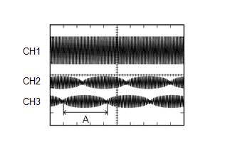
(f) Waveform 6 (generator resolver signal)

Item

Content

Terminal

CH1: C61-8 (GRF) - C61-9 (GRFG)

CH2: C61-10 (GSN) - C61-11 (GSNG)

CH3: C61-13 (GCS) - C61-12 (GCSG)

Equipment Setting

CH1: 10 V/DIV., 1 ms./DIV.

CH2: 5 V/DIV., 1 ms./DIV.

CH3: 5 V/DIV., 1 ms./DIV.

Condition

Generator resolver running

HINT:

The width indicated by (A) becomes shorter as the rotor speed increases.

    System Diagram

    Lost Communication With ECM/PCM "A" Missing Message (U010087,U029387,U117087)

    See More:

    Toyota Avalon (XX50) 2019-2022 Service & Repair Manual > Lane Departure Alert System (w/ Steering Control)(for Hv Model): FCM Destination Information Uninitialized (C1AAA)
    DESCRIPTION When the forward recognition camera is replaced with a new one, the new forward recognition camera attempts to store the country specification information received from the main body ECU (multiplex network body ECU). If the forward recognition camera cannot store the country specificatio ...

    Toyota Avalon (XX50) 2019-2022 Owners Manual

    Toyota Avalon (XX50) 2019-2022 Service & Repair Manual

    © 2024 Copyright www.tavalon.net
    0.0171