DESCRIPTION There may be a
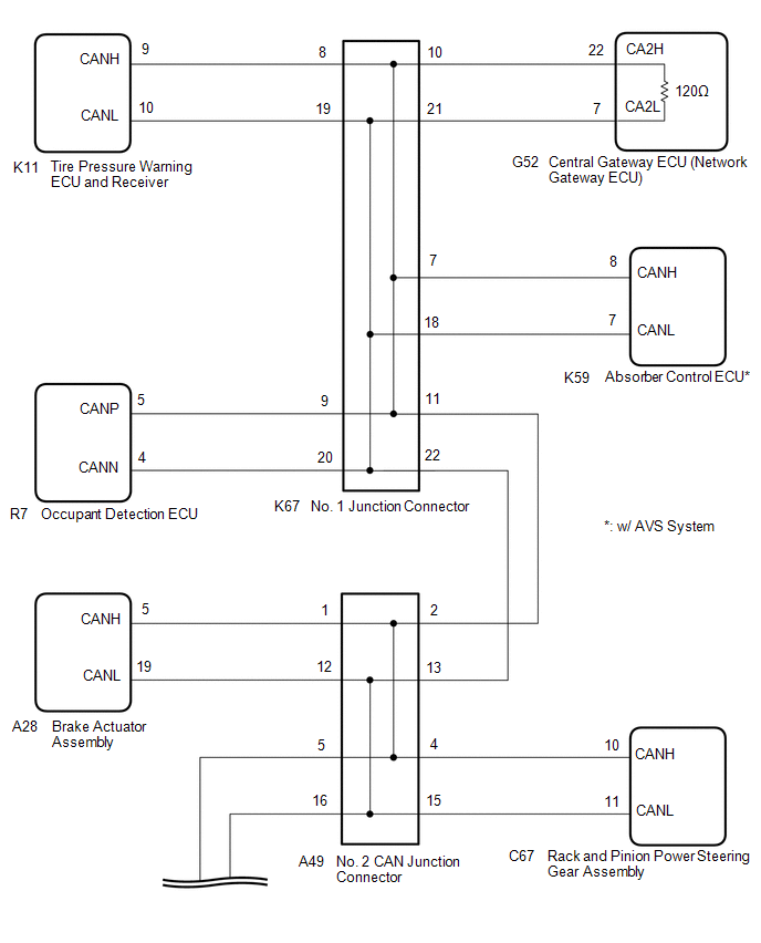
short circuit between the CAN main bus lines and/or CAN branch lines
when the resistance between terminals 22 (CA2H) and 7 (CA2L) of the
central gateway ECU (network gateway ECU) is below 54 Ω. |
Symptom | Trouble Area | |
Resistance between terminals 22 (CA2H) and 7 (CA2L) of the central gateway ECU (network gateway ECU) is below 54 Ω. |
- Short in CAN main bus lines
- Short in CAN branch lines
- Central gateway ECU (network gateway ECU)
- Occupant detection ECU
- Tire pressure warning ECU and receiver
- Rack and pinion power steering gear assembly
- Brake actuator assembly
- Steering sensor
- Airbag ECU assembly
- Absorber control ECU
(w/ AVS System)
- No. 2 CAN junction connector
- No. 4 CAN junction connector
- No. 1 junction connector
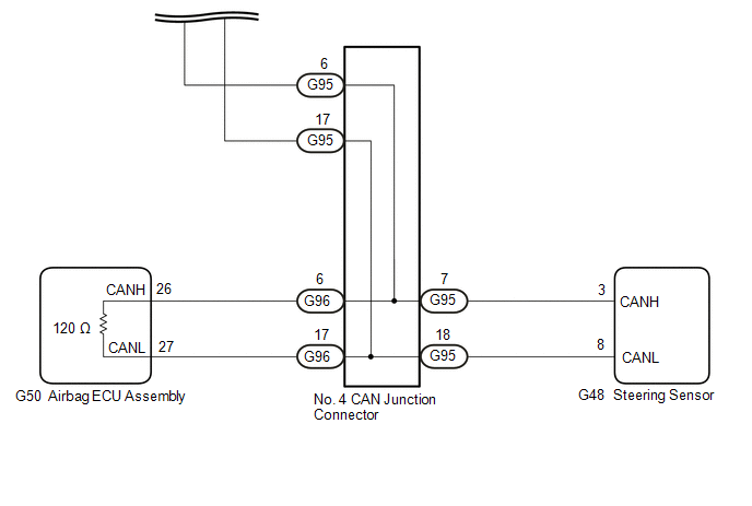
| WIRING DIAGRAM
 CAUTION / NOTICE / HINT
CAUTION: When performing the confirmation driving pattern, obey all speed limits and traffic laws.
NOTICE:
HINT:
- Before disconnecting related connectors for inspection, push in on each
connector body to check that the connector is not loose or disconnected.
- When a connector is disconnected, check that the terminals and connector body are not cracked, deformed or corroded.
PROCEDURE |
1. | CHECK FOR SHORT IN CAN BUS LINES (NO. 1 JUNCTION CONNECTOR) |
(a) Disconnect the cable from the negative (-) battery terminal. (b) Disconnect the K67 No. 1 junction connector.
(c) Measure the resistance according to the value(s) in the table below.
|
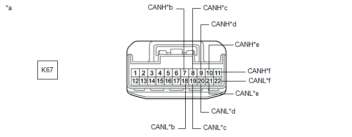
*a | Front view of wire harness connector
(to No. 1 Junction Connector) |
*b | to Absorber Control ECU
(w/ AVS System) | |
*c | to Tire Pressure Warning ECU and Receiver |
*d | to Occupant Detection ECU | |
*e | to Central Gateway ECU (Network Gateway ECU) |
*f | to No. 2 CAN Junction Connector |
Standard Resistance: |
Tester Connection | Condition |
Specified Condition | Connected to | |
K67-7 (CANH) - K67-18 (CANL) |
Cable disconnected from negative (-) battery terminal |
200 Ω or higher | Absorber control ECU* | |
K67-8 (CANH) - K67-19 (CANL) |
Cable disconnected from negative (-) battery terminal |
200 Ω or higher | Tire pressure warning ECU and receiver | |
K67-9 (CANH) - K67-20 (CANL) |
Cable disconnected from negative (-) battery terminal |
200 Ω or higher | Occupant detection ECU | |
K67-10 (CANH) - K67-21 (CANL) |
Cable disconnected from negative (-) battery terminal |
108 to 132 Ω | Central gateway ECU (network gateway ECU) | |
K67-11 (CANH) - K67-22 (CANL) |
Cable disconnected from negative (-) battery terminal |
108 to 132 Ω | No. 2 CAN junction connector |
|
Result | Proceed to | |
OK | A | |
NG (Line to central gateway ECU (network gateway ECU)) |
B | | NG (Line to No. 2 CAN junction connector) |
C | | NG (Line to ECU or sensor) |
D |
| A |
 | REPLACE NO. 1 JUNCTION CONNECTOR |
| C |
| GO TO STEP 3 |
| D |
| GO TO STEP 7 |
|
B |
 | |
| 2. |
CHECK FOR SHORT IN CAN BUS LINES (NO. 1 JUNCTION CONNECTOR - CENTRAL GATEWAY ECU (NETWORK GATEWAY ECU)) |
(a) Disconnect the G52 central gateway ECU (network gateway ECU) connector.
(b) Measure the resistance according to the value(s) in the table below.
|
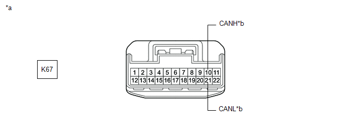
*a | Front view of wire harness connector
(to No. 1 Junction Connector) |
*b | to Central Gateway ECU (Network Gateway ECU) |
Standard Resistance: |
Tester Connection | Condition |
Specified Condition | |
K67-10 (CANH) - K67-21 (CANL) |
Cable disconnected from negative (-) battery terminal |
1 MΩ or higher |
| OK |
| REPLACE CENTRAL GATEWAY ECU (NETWORK GATEWAY ECU) |
| NG |
| REPAIR OR REPLACE CAN MAIN BUS LINES OR CONNECTOR (NO. 1 JUNCTION CONNECTOR - CENTRAL GATEWAY ECU (NETWORK GATEWAY ECU)) |
| 3. |
CHECK FOR SHORT IN CAN BUS LINES (NO. 2 CAN JUNCTION CONNECTOR) |
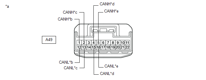
(a) Reconnect the K67 No. 1 junction connector. (b) Disconnect the A49 No. 2 CAN junction connector.
(c) Measure the resistance according to the value(s) in the table below.
|
*a | Front view of wire harness connector
(to No. 2 CAN Junction Connector) |
*b | to Brake Actuator Assembly | |
*c | to No. 1 Junction Connector |
*d | to Rack and Pinion Power Steering Gear Assembly | |
*e | to No. 4 CAN Junction Connector |
- | - |
Standard Resistance: |
Tester Connection | Condition |
Specified Condition | Connected to | |
A49-1 (CANH) - A49-12 (CANL) |
Cable disconnected from negative (-) battery terminal |
200 Ω or higher | Brake actuator assembly | |
A49-2 (CANH) - A49-13 (CANL) |
Cable disconnected from negative (-) battery terminal |
108 to 132 Ω | No. 1 junction connector | |
A49-4 (CANH) - A49-15 (CANL) |
Cable disconnected from negative (-) battery terminal |
200 Ω or higher | Rack and pinion power steering gear assembly | |
A49-5 (CANH) - A49-16 (CANL) |
Cable disconnected from negative (-) battery terminal |
108 to 132 Ω | No. 4 CAN junction connector |
|
Result | Proceed to | |
OK | A | |
NG (Line to No. 1 junction connector) |
B | | NG (Line to No. 4 CAN junction connector) |
C | | NG (Line to ECU or sensor) |
D |
| A |
| REPLACE NO. 2 CAN JUNCTION CONNECTOR |
| B |
| REPAIR OR REPLACE CAN MAIN BUS LINES OR CONNECTOR (NO. 2 CAN JUNCTION CONNECTOR - NO. 1 JUNCTION CONNECTOR) |
| D |
| GO TO STEP 7 |
|
C | |
| |
| 4. |
CHECK FOR SHORT IN CAN BUS LINES (NO. 4 CAN JUNCTION CONNECTOR) |
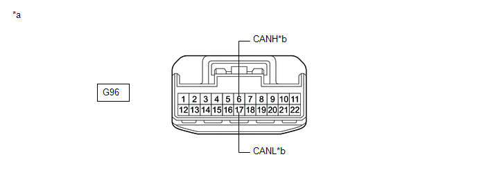
(a) Reconnect the A49 No. 2 CAN junction connector. (b) Disconnect the G96 No. 4 CAN junction connector.
(c) Measure the resistance according to the value(s) in the table below.
|
*a | Front view of wire harness connector
(to No. 4 CAN Junction Connector) |
*b | to Airbag ECU Assembly |
Standard Resistance: |
Tester Connection | Condition |
Specified Condition | |
G96-6 (CANH) - G96-17 (CANL) |
Cable disconnected from negative (-) battery terminal |
108 to 132 Ω |
| NG |
| GO TO STEP 6 |
|
OK | |
| |
| 5. |
CHECK FOR SHORT IN CAN BUS LINES (NO. 4 CAN JUNCTION CONNECTOR) |
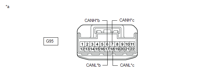
(a) Reconnect the G96 No. 4 CAN junction connector. (b) Disconnect the G95 No. 4 CAN junction connector.
(c) Measure the resistance according to the value(s) in the table below.
|
*a | Front view of wire harness connector
(to No. 4 CAN Junction Connector) |
*b | to No. 2 CAN Junction Connector | |
*c | to Steering Sensor |
- | - |
Standard Resistance: |
Tester Connection | Condition |
Specified Condition | Connected to | |
G95-6 (CANH) - G95-17 (CANL) |
Cable disconnected from negative (-) battery terminal |
108 to 132 Ω | No. 2 CAN junction connector | |
G95-7 (CANH) - G95-18 (CANL) |
Cable disconnected from negative (-) battery terminal |
200 Ω or higher | Steering sensor |
|
Result | Proceed to | |
OK | A | |
NG (Line to No. 2 CAN junction connector) |
B | | NG (Line to ECU or sensor) |
C |
| A |
| REPLACE NO. 4 CAN JUNCTION CONNECTOR |
| B |
| REPAIR OR REPLACE CAN MAIN BUS LINES OR CONNECTOR (NO. 4 CAN JUNCTION CONNECTOR - NO. 2 CAN JUNCTION CONNECTOR) |
| C |
| GO TO STEP 7 |
| 6. |
CHECK FOR SHORT IN CAN BUS LINES (NO. 4 CAN JUNCTION CONNECTOR - AIRBAG ECU ASSEMBLY) |
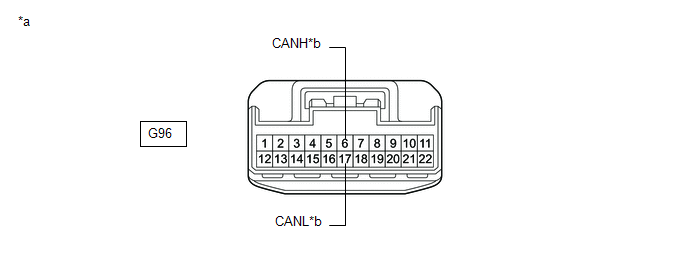
(a) Disconnect the G50 airbag ECU assembly connector. (b) Measure the resistance according to the value(s) in the table below.
|
*a | Front view of wire harness connector
(to No. 4 CAN Junction Connector) |
*b | to Airbag ECU Assembly |
Standard Resistance: |
Tester Connection | Condition |
Specified Condition | |
G96-6 (CANH) - G96-17 (CANL) |
Cable disconnected from negative (-) battery terminal |
1 MΩ or higher |
| OK |
| REPLACE AIRBAG ECU ASSEMBLY |
| NG |
| REPAIR OR REPLACE CAN MAIN BUS LINES OR CONNECTOR (NO. 4 CAN JUNCTION CONNECTOR - AIRBAG ECU ASSEMBLY) |
| 7. |
CHECK FOR SHORT IN CAN BUS LINES (ECU OR SENSOR) |
(a) Reconnect all wire harness connectors. (b)
Disconnect the connector that includes terminals CANH and CANL from the
ECU or sensor to which the short circuited branch line is connected. Click here

| (c) Measure the resistance according to the value(s) in the table below.
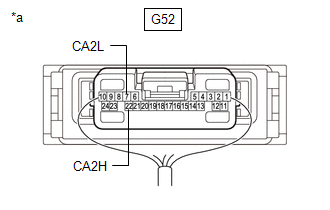
Standard Resistance: |
Tester Connection | Condition |
Specified Condition | |
G52-22 (CA2H) - G52-7 (CA2L) |
Cable disconnected from negative (-) battery terminal |
54 to 69 Ω |
HINT:
- If the resistance becomes normal (between 54 and 69 Ω) when the
connector is disconnected from the ECU or sensor, there may be a short
in the ECU or sensor.
- If the resistance does not become normal when the connector is
disconnected from the ECU or sensor, check for a short in the wire
harness and repair or replace the wire harness or connector if
necessary.
|
 |
|
*a | Component with harness connected
(Central Gateway ECU (Network Gateway ECU)) | | |
| OK |
| REPLACE ECU OR SENSOR |
| NG |
| REPAIR OR REPLACE HARNESS OR CONNECTOR | | 

