PRECAUTION NOTICE FOR INITIALIZATION NOTICE: When disconnecting the cable from the negative (-) battery terminal, initialize the following systems after the cable is reconnected.
*: When performing learning using the Techstream. Click here NOTICE:
CAN COMMUNICATION SYSTEM TROUBLESHOOTING (a) Because the order of diagnosis is important to allow correct diagnosis, make sure to begin troubleshooting using How to Proceed with Troubleshooting when CAN communication system related DTCs are output. Click here
(b) Precaution for steering system handling (1) Be careful when replacing parts. Incorrect replacement could affect the performance of the steering system and result in hazardous driving. Click here
(c) Precaution for SRS airbag system handling NOTICE: This vehicle is equipped with a Supplemental Restraint System (SRS) which includes parts such as airbags for the driver and front passenger. Failure to carry out service operations in the correct sequence could cause unexpected SRS deployment during servicing and may cause a serious accident. Before servicing (including removal or installation of parts, inspection or replacement), be sure to read Precaution for SRS. Click here
(d) Precaution for when disconnecting a wire harness from a CAN junction connector (1) When disconnecting a wire harness from a CAN junction connector, use tape or tags to identify each connector and make sure to reconnect each connector to its original location on the CAN junction connector. HINT:
(e) Bus line repair (1) After repairing a bus line with solder, wrap the repaired area with electrical tape. 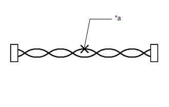
NOTICE:
(2) Do not use bypass wiring between connectors. 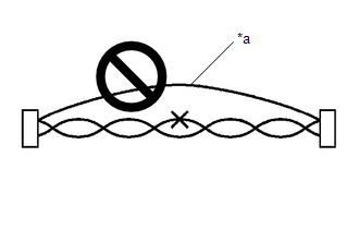
NOTICE:
(f) Connector handling (1) When checking resistance with a tester, insert the tester probes from the backside (harness side) of the connector. 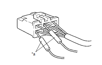
(2) When it is not possible to insert the tester from the backside of the connector, using service wires, measure from the front side of the connector. 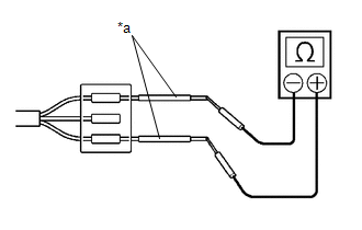
(g) Precaution for when replacing a gateway function equipped ECU (sub bus monitoring ECU) (1) When replacing a gateway equipped function ECU (sub bus monitoring ECU) with one which was installed to another vehicle, perform initialization of the sub bus monitoring ECU in order to clear stored bus information. Click here
NOTICE: If the stored bus information does not match the current sub bus configuration, DTCs may be stored and fail-safe functions may operate. HINT: It is not necessary to perform initialization of a gateway monitoring ECU (sub bus monitoring ECU) when using a sub bus monitoring ECU which was installed to another vehicle with the same sub bus configuration. (h) Precautions for when a gateway function equipped ECU (sub bus monitor ECU) detects communication DTCs for ECUs not connected to the ECU (1) Refer to precautions when replacing a gateway function equipped ECU (sub bus monitoring ECU) and initialize the connection information of the ECU. (2) Clear the DTCs and check that no DTCs are output. (i) Difference between genuine navigation receivers/radio and display receivers and optional navigation receivers/radio and display receivers (1) Some optional navigation receivers/radio and display receivers are available as CAN compatible devices. Be aware that some optional navigation receivers/radio and display receivers do not have the same diagnostic features or characteristics of genuine navigation receivers/radio and display receivers. NOTICE:
|
Toyota Avalon (XX50) 2019-2022 Service & Repair Manual > Knee Airbag Assembly(for Driver Side): Components
COMPONENTS ILLUSTRATION *A for HV Model - - *1 LUGGAGE TRIM SERVICE HOLE COVER - - ILLUSTRATION *1 COWL SIDE TRIM SUB-ASSEMBLY LH *2 FRONT DOOR OPENING TRIM WEATHERSTRIP LH *3 FRONT DOOR SCUFF PLATE LH *4 HOOD LOCK CONTROL LEVER SUB-ASSEMBLY *5 INSTRUMENT SIDE PANEL LH *6 LOWER NO. 1 INSTRUMENT PANE ...


